
“I made this really amazing PCB for INTEL 8051 microcontroller in the form factor of an Arduino UNO. See how to build your own one.
Hello Guys, Once again I have made a microcontroller Development board but this time we are using INTEL 8051. Yeah! I know it is pretty old and it is the first microcontroller I had started with. It was the 1st microcontroller of INTEL, released back in 1980, and the computer era started from there. This is very popular and even nowadays there are few applications like calculators, Automotive applications which are running on it. In the 1980’s there was no concept of flash ROM and even at that time this MCU came with Harvard architecture in which code and data memory are separated from each other.
But nowadays as microelectronics grow some custom solutions are available which are utilizing the same die of microcontroller as a brain but with added peripherals like onboard flash, Extra RAM, 2 cores on a die, higher crystal compatible circuitry, onboard programming control and which may give this higher performance. INTEL is not manufacturing this microcontroller now, but there are some 3rd parties which are making custom solutions as per specified applications. The original microcontroller is rarely available in the market, because the production was stopped many years ago.
Original 8051 Features:
- 40 pins DIP (dual inline package),
- 4KB of ROM storage
- 128 bytes of RAM storage
- 2 16-bit timers
- Low-power Idle and Power-down Modes
- It consists of four parallel 8-bit ports (32 Programmable I/O Lines)
- An on-chip crystal oscillator having crystal frequency of 12 MHz
80s52 Custom 8051 microcontroller:
- 8KB of In-System Programmable (ISP) Flash Memory
- 4.0V to 5.5V Operating Range
- Fully Static Operation: 0 Hz to 33 MHz
- 256 x 8-bit Internal RAM
- 32 Programmable I/O Lines
- 3 16-bit Timer/Counters
- Eight Interrupt Sources
- Full Duplex UART Serial Channel
- Low-power Idle and Power-down Modes
- Interrupt Recovery from Power-down Mode
- Watchdog Timer
- Dual Data Pointer
As you might see, the performance of a microcontroller depends on architecture, clock rates and Design logic. 80s52 has higher performance and better features than Original microcontroller with 8KB onboard Flash as program memory. Here is the link to the full datasheet, explore the datasheet for operation related knowledge.
Components Required:
- 80S52 microcontroller (8051)
- 40 PIN IC Socket
- 0603 LEDs
- 1K and 10K resistor
- 10uf, 100nf, 33pf capacitors
- 12MHz crystal oscillator
- USB type C
- Pin Headers
- AMS1117 5V Regulator
- 12V Jack
- Reset Switch
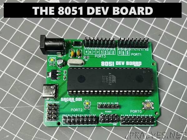
We need an activation circuit to program this microcontroller, which contains a reset circuit, programming headers, crystal oscillator and some loading capacitors. That is known as minimal system required for a microcontroller, still there are some issues remain which has to be resolved like power supply, headers for I/O and programming pins. So, I designed a development board rather than making a minimal system. Which allows to directly connect the peripheral on I/O ports of the microcontroller. I took inspiration from Arduino UNO and designed a PCB with all the controls on it, the programming headers are placed on one header, and all the 4 ports have dual headers. I also designed the power section with some capacitor, Dc jack and linear voltage regulator on the same board.
8051 required a pull up resistor on reset pin which is used to perform all the operation and this pin never kept floating, and a tactile switch is added to pull down the reset pin to Reset the overall microcontroller and to resume the operation from beginning. I am using a 12MHz capacitor with 33pF loading capacitors as mentioned in the datasheet, the loading capacitor is used to tune the crystal frequency precisely over the PCB impedance. In the power section I am using a linear voltage regulator AMS1117 5V @1A which supplies 5V to the whole microcontroller and headers. Some coupling capacitors are added with it, to remove any transient produced in the power supply (basically smoothen out the DC voltage noise).
There are two power supply sources, 1st 12v barrel jack and 2nd the type C USB. Both will allow the power input, USB interface is just used as a power supply source here not for programming. Two onboard status LEDs are there one for the power supply and second to test the blink program for 1st time programming testing, The blink LED is connected to port 2 pin 7. Two extra headers are there, one for controlling the operations(U7) and another one to program the microcontroller (H2). Controlling sections have control on switching of ROM(external/internal), Data and address bus multiplexing control and control on program status. Programming headers are utilizing the SPI interface to connect with the microcontroller.”