
“Zen and the pursuit of CW operation with SDR Console.
After a few on-air queries, I decided to write this article which documents how I operate CW using my SDR based QO-100 groundstation. The circuit I designed incorporates the necessary functions into a single operational device. It avoids some of the CPU and SDR overhead associated with PC applications and any virtual audio cabling.
Since the SDR hardware and software has no easy way of easily generating a CW signal directly, I use an injected audio tone in SSB mode. It was an emission type often referred to as A2A when I first took the RAE in 1985. It is not a new technique and is already in use by some other QO-100 operators. This unit conveniently combines all the useful functions which are necessary to operate CW through the satellite’s NB transponder into one box.
It can also be used if using traditional analogue radios through QO-100. Where the CW is directly transmitted as A1A by the uplinking radio in the normal way. Here, we can still use the unit’s memory keyer, receiver mixer and QSK Break-In functions.
The project was an exercise in opamp design and noise elimination. Overcoming superfluous noise by designing with different grounding options and component choices was particularly challenging. I have included a complete schematic walkthrough with circuit description. Links to datasheets and other relevant information are included.
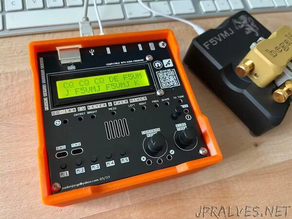
This is the first project for which I have not had to code any firmware for. There are already many good CW keyer projects in existence. The K3NG code by Anthony Good probably provides the most complete keyer firmware available. It is fully configurable and has many options. My final schematic and subsequent PCB is compatible with the K3NG sketch and the Arduino MEGA 2560 R3. This providing all the options are correctly set in the keyer’s sketch files.
INTRODUCTION
Any CW operator will tell you that once this mode is minimally mastered it will quickly become the preferred mode of choice. CW’s efficiency in relaying messages across the globe are unsurpassed. Despite FT8’s better signal to noise performance, CW surpasses it as a communication mode when you considered that you are not limited in the contents of the message exchanged, as well as the simplicity of the equipment normally needed to become QRV.
Most CW on the NB transponder is generated in the classic way by the keying of modern CW capable transceivers. Two radios are often simultaneously used for uplink and downlink duplex operation. For efficient CW operation with headphones, we need to mix both our transmitted sidetone with the signal received. A headphone audio mixer is necessary.
Other operators, like myself, use SDR Pluto based groundstations with PCs running SDR software. This combination does not give an easy way to transmit CW code over QO-100. Sometimes SDRs have a CW key input jack (eg. the HF SDR Hermes Lite 2) but the Pluto does not. Here I use the Kafkaesque method of producing a clean carrier in SSB mode by injecting in a pure audio tone. Other amateurs have already faced a similar dilemma and have used this eclectic solution. Be warned however, that this method may not give perfect results when using PCs, soundcards and SDR software. Your Milage May Vary (YMMV).
CW SOFTWARE AND VIRTUAL AUDIO CABLES
Some CW operators have used software like ‘CWType’ and ‘Morse Keyer 4.3’ with Virtual Audio Cables to feed in the tone to SDR Console in SSB mode. A paddle can be connected to the PC serial port via a simple homebuilt interface circuit. Serial to USB converters are also available if your PC does not have a serial port. Eduardo Erlemann PY2RN has good YouTube videos of how to do this and I would recommend trying this method first.
Eduardo Erlemann PY2RN channel:
- ADALM Pluto / Lime SDR etc. How to use a real Keyer to make CW!
- Making CW using SDR Console, Pluto SDR and FLDIGI
More often than not however, even with the most powerful machines, the CW flow is not smooth because of how the PC has to manage it’s workload. Although mitigated, since the unit described here still has to work with a soundcard and SDR software, inherent timing delays and glitches may still manifest themselves. YYMMV, so please read the Caveats section below.
FEATURES
- Low noise high performance mixing and headphone amplifier section.
- High performance TPA6111A2 stereo headphone amplifier by Texas Instruments.
- Low noise Texas Instruments OPA4134 opamp audio mixer.
- Separate PCB grounding sections to quell noise.
- Power isolation using a Murata NKE0505SC subminiature DC/DC Converter.
- Symmetrical power supply with an LM2664 charge-pump voltage inverter.
- Clean sinusoidal Twin-T audio oscillator.
- Sidetone level adjustment (with High, Medium, Low).
- Individual Left and Right channel adjustment of received audio.
- Transmit tone frequency control.
- Transmit tone level control.
- Tone envelope edge shaping control.
- Rx Mute jumper for full-duplex or QSK break-in operation.
- Configurable QSK break-in delay time.
- CW or SSB selection switch with warning LED.
- TRRS (CTIA) headset 3.5mm jack socket.
- Simple connection to most gaming headphones using TRRS (CTIA) jacks.
- TRRS (CTIA) soundcard (or radios) 3.5mm jack socket.
- Simple straight through TRRS (CTIA) cable required to connect soundcard.
- Illuminated 16x2 LCD display.
- LCD brightness and contrast controls.
- LED indicators for TX1, PTT1, TX2 and PTT2 status.
- Three for LEDs indicating Command Mode and sending practice response.
- Powered from Arduino Mega board’s USB port (PC/MAC) or barrel jack.
- Command Line Interface (CLI) through USB port.
- Compatible with WinKeyer by K1EL or variants like Mortty.
- Automatic Software Reset (ASR) enable/disable jumper.
- Both CLI or WinKeyer operation can be selected on same USB port.
- Direct microcontroller reset available on shield.
- PS/2 mini din keyboard input, for CW sending and commanding keyer.
- Paddle or straight key input, 3.5mm stereo jack socket.
- Two transmitter outputs (TX1 and TX2), 3.5mm stereo jack sockets.
- Keying and PTT line on each transmitter jack output.
- Optoisolation of receiver muting line from the microcontroller.
- Optoisolation of tone oscillator control line from microcontroller.
- Rotary encoder with push button for Command Mode.
- Five on board memory push buttons.
- On board piezo sounder.
- Piezo sounder volume control.
- Shield fits cheap and ubiquitous Arduino MEGA 2560 Rev.3 board.
- Uses a 10x10cm double sided PCB for cheaper fabrication.
- SMD components for compact form factor.
- Six pin Options header for Goertzel decoder is available.
- I2C four pin header port is available.
- Compatible with the many features of the K3NG keyer firmware.”