
“This power source is intended for Dash cameras permanent power supply. Compared to commercial models, it has 50 to 100 times lower consumption in the off state.
I bought a commercial MiVue SmartBox lll, but it is not as smart as it is called. In the “power off mode” when the camera is turned off due to low voltage, it still draws about 3.5 mA from the car battery! In other words, every 12 days it consumes 1 Ah from your car battery. If you add this 3.5 mA to the “normal consumption” of a switched-off “modern car” (which is 2 to 30mA) then, after long-term parking in cold conditions (or if your battery is old) it can cause the car will not start.
This circuit will help you to save your car battery. My power source for dash cam will takes 1Ah from your battery during 830 days (more then 2 years) not just 12 days! I thing only now it is possible to call the mode “power off mode” even if it is actually still stand by mode.
Notes:
If you do not need the “Power Off” function at the pre-programmed voltage level and you also don’t need timer, then you simply do not solder the chip (and its components) to PCB. In such a case the device will work as standard 12V to 5V converter controled by ACC input. The “Power Off” consumption will stay on 50uA.
Possibility to use in 24V vehicles. Then change value of R21 to 6.8k and R17 to 47k. Capacitors C4,C8,C11 have to be for minimal 35V! C8 minimal capacitance is 470uF! (recommended is 680uF). Small changes in the source code are also required but nothing problematic to do. Later on I will write the “universal version” of source code. Yes, there is the “Universal value” for R21, R17 working in both car 12V and 24V. The values are R21 9.1k, R17 45.3k. but not so easy to buy E96 decade value. Voltage on microcontroller pin must not be higher than 5V!
Supplies:
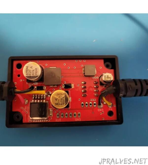
I designed the PCB so that I could use the box and cabling from the commercial product SmartBox lll. (I will make a 3D model of the box in the future).
The basis is the LM2596M-5.0V converter from China. Yes, you read correctly from China. It has the same designation as the original LM2596. I made device from both, the original and the Chinese copy. There are three differences:
1. The original works at a frequency of 150kHz, the Chinese at 56kHz - the original is better here
2. The original in OFF mode takes 170 uA even though according to the catalogue it should have 80 uA! Chinese takes only 50uA! (I tried three pieces)
3. I bought ten pieces from China for the price of one original from DigiKey.
For simplicity and general extension of Arduino, I used the same ATmega328 processor in the design. - We will create our own Arduino from the PCB by burning the bootloader into the processor. For this we will need, for example, an Arduino Uno.
You will need software Arduino IDE and programmer to program the PCB. Write “Mini USB To FT232 TTL” to ebay or AliExpress to find programmer similar to pictured. The pins on the programmer are in order: DTR, RXI, TXO, VCC, CTS, GND.
other parts according to the schematics diagram. Used crystal is 3.2 x 2.5 mm in size, for example DigiKey ECS-160-9-33B-CKY-TR. Resistors are 0805 size except R18, R20. Capacitors size is also 0805 except high value capacitors 10uF and above. Switch Digi-Key Part Number 2449-KG04E-ND or similar from China for 1/10 of the price :-). I bought switches here . Inductors I used are: 47uH MGAH1004470M-10 and 6.8uH MGAH06036R8M-10”