
“The Arduino Launch Control System is a model rocket launch controller for a single rod launch pad. This was the first Arduino rocketry project that I wanted to design and build, having just started into learning about electronics and the Arduino less than 6 months prior. There are a number of Arduino model rocketry launch projects available on the Internet, and they did provide inspiration for this project. Yet while they provided some great ideas, I wanted to approach this launch control system from a different angle.
Focus on Research
If you look around my web site (https://rocketryjournal.wordpress.com), you know that I often discuss how model rocketry can be used to explore both science and technology. One great way to combine these is to use model rocketry as part of a science or technology fair project.
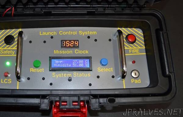
If you are using a model rocket in a research project, no doubt weather will be a part of your data collection efforts. To help meet this need the launch control system provides the user with several weather data points, including:
Temperature
Humidity
Barometric Pressure
In effect, the project has a small, built-in weather station.
Focus on Safety
Safety is always an important consideration in rocketry. As I was designing the Arduino Launch Control System (LCS) I wanted to make sure that it would be safe to operate. The LCS provides a ten-second countdown and I wanted to be sure that when the counter hit zero, the Launch Control Officer still wanted the rocket to launch. In order for the countdown to start and power to be supplied to the launch pad, I decided that several things must be accomplished.
The LCS has two independent power supplies and both must be turned on. The power must be turned on to the launch pad or there will not be any power at the igniter clips. Second, the key switch must have the key inserted and turned on. Without the key, the switch will not turn on. Without the switch being turned on, power will not flow from the launch battery to the relay and on to the launch pad. The key switch LED also indicates if there is continuity to the igniter in the rocket.
However, if you only turn on power to the launch pad you will find that the continuity lamp will operate but the fire and safety buttons are inoperative. You must also supply power to the Arduino. The system will not fire without the Arduino being powered up, as it reads the signals from the fire and safety buttons, which sends the signal to the relay. The relay allows the power to flow to the launch pad.
Finally we come to the Fire and Safety buttons. To start the countdown both buttons must be pressed down. Additionally, they must remain pressed down during the countdown. If either button is released, the countdown will stop and the launch is aborted.
You will notice that the fire and safety buttons are located at opposite ends of the LCS. This design decision helps negate the possibility of an item falling on the fire button leading to an accidental launch. The use of the key switch, dual power supplies and the requirement for both buttons being continuously pressed all brings additional layers of safety into the system to help prevent accidental launches.
Focus on Usability
I wanted the system to be easy to use and portable. If it is not easy to take out to the flying field, no one will use it. I tried to keep the cost low and while it does cost more than a plain Estes launch controller, it does a lot more too!
I especially wanted this system to be something that middle or high school students could build as part of an overall science and technology project. I wanted it to be more than just a launch controller; I wanted it to be a learning experience. I wanted it to have the ability to spark interest in rocketry, electronics, research and more.
I also thought of this as the baseline system. Over time it could be expanded with additional sensors or other options. The LCS presented here shouldn’t be the end, but rather the beginning.
Finally, it had to look cool. If it doesn’t look cool, well, it just has to look cool!!
Supplies
- Hyper Tough 13-inch Tool Box
- Nano Board CH 340/ATmega+328P
- Panel Mount Type Mini USB 5Pin Male to Female Extension Adapter Cable
- 2 Pin Metal Male Female Panel Connector 12mm GX12-2P Silver Aviation Plug
- Cabinet Pull Polished Chrome 3 inch (76 mm) Center to Center
- SPST Momentary Push Button Switch
- One Black
- One Red
- Keyswitch Keylock Switch with Keys
- BMP180 Barometric Pressure Temperature Sensor Module
- PCB Prototype Boards
- 1 Channel Relay Module Board
- SPST Latching Type ON/OFF Push Button Switch
- 4-Digit Tube LED Segment Display Module
- 4 AA Battery Holder with Leads
- 9V Battery Connector
- LCM1602A LCD Screen
- DHT11 sensor
- 15mm Carbon Potentiometer
- LEDs 5mm RL5-R5015 - Super-Red LED
- LEDs 5mm RL5-G8020 - Super-Green LED
- DS1307 Real Time Clock
- Piezo Buzzer
- 510 ohm resistor
- 1K ohm resistor”