
“The CMOS series of integrated circuits appeared shortly after the TTL series. This means that at the beginning of the 70s it was available on the market in an accessible way for any user. Hence the nostalgia of those who used these circuits and who remember those years. Today, these integrated circuits are considered outdated, but building a device that uses them can bring back pleasant memories, can bring back into use components that would otherwise constitute electronic waste, and last but not least, a useful device could be obtained in the electronics technician’s laboratory.
The HCMOS series appeared on the market a little later and had, in addition to CMOS (low consumption and higher degree of integration compared to TTL), an increased working speed. The latter can be used at over 60 MHz.
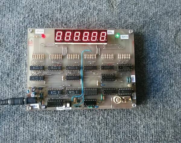
The device uses 3X HCMOS integrated circuits, the others being CMOS. The two families interface directly, without problems. In this way, a high working speed is obtained, with low consumption. Single supply voltage of 5V. Fewer integrated circuits are used than in the case of TTL, resulting in a more compact device.
Supplies
Integrated circuits can be recovered from old computer systems, old instrumentation devices and others. LED displays can be recovered from old instrumentation boards, analog satellite receivers or others.
All the components that make up this device are in current production and can be purchased from websites specialized in sale of electronic components, at convenient prices.
We start from a 4MHz oscillator, made with Z1 and U1. A CMOS circuit does not work at this frequency and powered at 5V. This is the reason for choosing an HCMOS circuit as an oscillator. Also for reasons of working frequency, I also chose U2 from the HCMOS series. It divides by 4, at its output having a signal with a frequency of 1MHZ.
The other integrated circuits are CMOS, with the exception of U8, which is HCMOS, also chosen for reasons of working at higher frequencies.
The 1MHz signal is applied to pin 2 of IC U3, CD4518. This IC contains two frequency dividers by 10, so that at its output (pin14) a 10KHz signal is obtained.
There are two more stagess of these, made with U4, U5.
A 100HZ signal (0.01s) is obtained at pin 14 of U4. At pin 7 of U5 we will have a 10Hz signal (0.1s). These two signals will give the frequencies of the ”Time Base”, in this case in number of 2, selectable with Sw1. The second section of U5 is not used.
The “Time Base” signal selected by Sw1 is divided by 2 by the first section of U6, obtaining a signal with a fill factor of 50% (0,1s+0,1s or 0,01s+0,01s).
During the first period of time, the input pulses are counted, and at the end of this period, the monostable made with the first two gates of U7 is activated, which then activates the second monostable made with the next two gates of U7.
At the outputs of these two monostables there are the 2 short pulses for loading thecount memory, followed by the counter reset pulse.
Then the cycle of counting, memorizing and resetting starts again.
The CMOS level signal, whose frequency we want to measure is applied to pins W1, W2 (Fin). They pass through the corresponding gate from U1, which is open for a duration given by “Time Base” (0,1s or 0,01s).
These pulses are applied to pin1 to U8, which is a double divider with 10 made in HCMOS technology.
The use of this type of integrated circuit allows the measurement of frequencies above 60 MHz.
The next two integrated circuits, U11 and U14 are also double dividers by 10 and together with U8 is the main counter of the frequency meter.
U9, U10, U12, U13, U15, U16 have the role of storing the pulses counted by the main counter, decoding the obtained numbers and being the drivers for common cathode LED displays (U17, U18, U19), through 220 ohms current limiting resistors.
Q1, Q3, U6 is the signal circuit for exceeding the measurement range, which is signaled by D2 blinking.
D1 lights up flashing in the rhythm of the time base, through Q2.”