
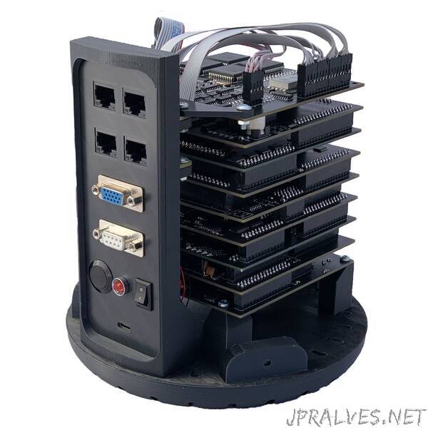
“32 bit RISC-V homemade
In this article I will describe how I designed and made a functional 32 bit RISC-V CPU at home.
Specifications:
“Max” clock speed: 500 kHz
Program memory: 512 kB
RAM size: 512 kB
VGA Output: 200x150 px (black and white)
2x 8-bit Input ports
2x 8-bit output ports
DETAILS
Almost every electronics device uses some kind of a microcontroller nowadays. The thing is, that these chips can be very complicated, and even though you can buy them very inexpensively (like Arduino for example), I’ve still wanted to take a deeper look into them and understand their inner workings. I soon realised, that I have only a few options to do that:
Study an existing microcontroller from a datasheet
Make some kind of a emulator (C / Python)
Build my own CPU from scratch
You can already guess which path I took.
1. Designing my own CPU:
I discovered Ben Eater’s homemade CPU on Youtube and I was so mesmerised and almost immediately got to work. I’ve improved his design and built myself an 8 bit CPU too. This article is not about that one though. If you want to, you can check out my photos in this Twitter post. I may write another article about that someday.
At this point, I had a pretty good understanding of a really basic CPU, but for some reason, this wasn’t enough for me. Shortly after that, I’ve stumbled across Robert Baruch’s Youtube channel and he started working on a 32 bit RISC-V CPU, which also used just a basic logic components. I have done some research about RISC-V and found out, that it is completely open-source and well documented.
Me being me, I started making my own RISC-V CPU implementation in a program called Logisim-Evolution. Again I set my goal not use ANY microcontrollers or FPGAs in my build - just basic discrete logic components. So, what exactly am I going to build? I needed to NOT set too a high goal for myself, so I would be able to finish this project in relatively short time (Is 2yrs short enough? :-) ). The most basic RISC-V CPU, that is supported by compilers, must include the extension “I” (Integer) and it must be at least 32 bit. So now I had all the information I’m going to need, so it was time to start building. Oh, and did I mentioned that I was going to put a VGA output card on as well? (VGA card inspired by Ben Eater; https://eater.net/vga)
After 6 months of fiddling with Logisim, I had a working “simulation”. The next step would be to create schematics for all of the modules, design all PCBs and order them from JLCPCB. But, as this would be my first time ordering PCBs, I didn’t want to screw up everything - so I separated the design into modules, and chose few at a time, so as to not overwhelm myself. JLCPCB had a discount for a 2 layer PCB with dimensions < 100mm x 100mm, and I’ve tried my best to fit into these dimensions to keep the lower cost (and I’ve managed to fit it in!).
So, now I have a working simulation and my plan is to take few modules at a time, turn them into proper schematics, make a boards and order them. This isn’t the best way to do things, but otherwise it would be too much for me. (foreshadowing)”