
“Previously I introduced Arduino base Sound Level Meter circuit (From hereinafter as SLM) circuits using simple LEDs.
This time let’s change the visual effect with a more multifunctional 8x8 LED dot matrix display.
Although the previous SLM used Adafruit MAX4466 MIC-Amp break-out, this time the old is but good pre-amplifier circuit that utilizes op-amps (NE5534, TL071) is reused for capturing audio signal.
When using a single line (with 10 LEDs) of the sound level display, only present audio input is suddenly displayed and disappears quickly without showing any trend of sound strength changes.
That’s why I’m considering using an 8x8 LED dot matrix.
As the LED matrix support 8 lines of display space, it can show 8 times of sound level change when input data shift consciously to the left.
If you cascade two LED matrixes, you can see a total of 16 frames of audio sound level changes.
As a result, you see a change of sounds in a more interesting manner.
Let’s look at more details about this new SLM device.
When you looked at the schematics above, the same old pre-amplifier circuit is reused instead of the Adafruit MAX4466 MIC-Amp breakout board.
The sound voltage captured by electrets MIC fed to pre-amplifier and subsequently connected to analog A0 port of the Arduino Uno board.
As this pre-amplifier requires 12V input voltage, the same voltage of the power supply is connected to the Arduino Uno board.
The Arduino Uno board has a circular-shaped power socket (Usually it is connected with a 9V~12V wall socket adapter) and output power from LM7812 is directly connected to this socket.
When you buy two units of hardwired 8x8 dot matrix display, you don’t need to solder anything.
But as bought two separate 8x8 dot matrix displays, I need to connect 5 lines (Vcc, GND, DIN, CS, CLK) of matrix modules.
Overall hardware wiring for this circuit is relatively easier than others as only 5 lines are connected between the dot matrix display and Arduino.
But controlling the two 8x8 dot matrices is not easy and entirely dependent on the sketch program that will be explained in other steps below.
For simplifying overall circuitry, I didn’t add 100K potentiometers used in the previous Arduino-based SLM shown in the project page link below.
https://www.instructables.com/Sound-Level-Meter-With-Arduino/
Instead of adding a complex sound level controlling mechanism (base and gap control) with two VRs, careful sound level calculation is carried out and applied to the sketch program.
I’ll explain in detail how LEDs are controlled with pre-defined sound level threshold values.
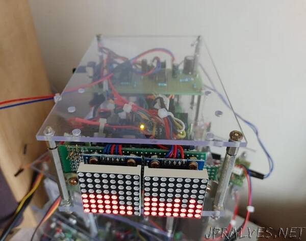
The most important part of this SLM is the 8x8 dot matrix displays that can be seen on the bottom side of the picture shown above.
As I bought two individual 8x8 dot matrix modules, 5 wires are soldered together and two displays are mounted on universal PCB and fixed together.
The following parts are used for this SLM circuit.
***
The pre-amplifier requires the following parts.
- FQ-057 electrets MIC
- NE5534, TL071 op-amp IC
- 1/4W 47K, 100K, 10k, 27K, 22K resistors
- Potentiometer 10K
- Electrolytic capacitors 2.2uF, 4.7uF x 2EA, 10uF x 2EA all rated more than 50V
- Film capacitors 100nF 50V
***
For the controlling and sound level displaying, the following parts are used
- Arduino Uno board, 5V
- 8x8 dot matrix module x 2EA
- LM7812 regulator
- 0.33uF film and 0.1 ceramic capacitors
- Wires, Pin-head, Universal PCB
- Acrylic boards, metal PCB supporters
***
As I introduced many other SLM circuits, I’ll not explain details about parts used, wiring components together, and soldering all parts on PCB.
You can see other Instructables for details about wiring and soldering of all parts explained above.”