
“Building a simple 7 segment display counter using ATtiny microcontroller.
Overview
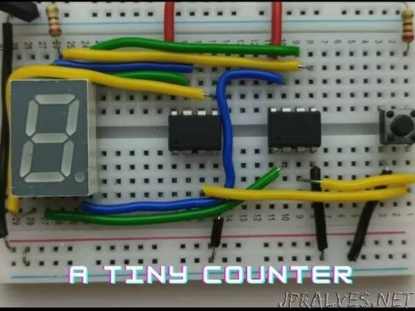
In this project, we will be controlling the 7-segment display using 2-ATtiny microcontrollers which get input from the push button and increment the number. The ATtiny will be programmed using an Arduino Uno through ISP mode. Now let’s get into the project.
Components
Let’s begin with taking a look at the individual components used in the project.
ATtiny:
ATtiny (also known as TinyAVR) is a subfamily of the popular 8-bit AVR microcontrollers, which typically has fewer features, fewer I/O pins, and less memory than other AVR series chips. ATtiny85 is an 8-pin – 8bit AVR – RISC microcontroller that has a single bi-directional IO port ( Port B with 6 pins; PB0 to PB5), a 10-bit analog-to-digital converter, fully functioning 4 wire SPI, and two 8-bit timers. It has :
Flash memory of 8Kb to store programs.
EEPROM memory of 512 bytes to store the data.
SRAM of 512 bytes can be used during program execution and temporary data storage. 32 GPR (general purpose registers) are attributed to serving the purpose.
7 SEGMENT DISPLAY:
A 7-segment display is an electronic display device that is used to display numerical. The seven LED segments of the display and their pins are “a”, “b”, “c”, “d”, “e”, “f”, and “g” as shown in the figure given below. Each of the pins will illuminate the specific segment only. Power (or voltage) at different pins can be applied at the same time, so we can form combinations of display numerical from 0 to 9. Each display unit usually has a dot point (DP), which could be located either towards the left or towards the right of the display pattern.
Types of Seven Segment Display:
Common Cathode - Here, all the cathode pins are connected to the ground or logic 0. The other anode pin is taken out and is given to high or logic 1 signal to illuminate the particular led segment from “a” to “g”
Common Anode - Here, all the anode pins are connected to a high pin or logic 1. The other cathode pin is taken out and is given to ground or logic 0 signal to illuminate the particular led segment from “a” to “g”.
In a common cathode, all the cathode pins of seven LEDs are connected, whereas in a common anode all the anode pins are connected. We will be using a common anode display.”