
“Compares solar irradiance performance between fixed system and a tracking system
About this project
This project compares solar panel irradiance between two well-known systems – fixed vs. tracking. Most solar generation systems used for residential areas have fixed solar panels, frequently mounted on the roof. Some solar generation sites have panels mounted in the fixed but optimal angle that can be used year-round. Some sites use adjustable tilt angle panels whose tilt angles are adjusted each season to improve efficiency.
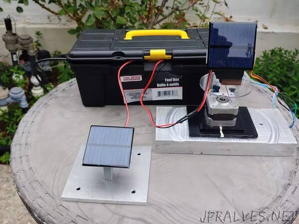
This project will have two solar panels – one is fixed (orientation and tilt) and the other tracks the sun and compare solar irradiance performance of the two systems. For tracking system, the solar panel’s tilt angle is adjusted by a servo motor, and the servo motor is mounted on the stepper for orientation adjustment. From morning to evening, orientation and tilt angle are adjusted to improve solar irradiance. By comparing this with that of fixed panel, net benefit of solar tracking over fixed system is obtained.
The CAD model shows how the tracking system is constructed. A solar panel is attached to a servo motor with a 3-D printed adapter, and the servo motor sits on the acrylic disk glued to the stepper motor.
Sun angle calculation
There are quite a few sites that provide how to calculate Sun’s angle (elevation and azimuth) at a certain location. This project uses the following website to have sun’s elevation and azimuth angles at a specific day and time. This information is entered in the code and the stepper motor and servo motor are used to adjust tilt and orientation of the panel to match the entered data.
How to measure solar irradiance
There is a published project that compares irradiance performance of solar panels using a simple resistor circuit. This method is simple but effective, and also lets the user select solar panels having minimal variation in of performance.
In this project two pre-characterized toy-grade solar panels are used. The nominal specs are, 60mmx60mm, 5.5V, 80mA. Voltage across the resistor is measured every 15 minutes, from 8am to 6pm.
Stepper motor control
Nema 17 bipolar stepper motor is controlled by A4988 stepper motor driver. The stepper motor has 1.8deg step angle which provides a good resolution for orientation without micro-stepping.
16 VMOT — stepper motor power supply + terminal
15 GND — stepper motor power supply Gnd
10 VDD — Arduino 5V
9 GND — Arduino Gnd
5 RST and 6 SLP are tied together
1 EN, 2 MS1, 3 MS2, and 4 MS3 are left open (full step mode)
7 STEP — Arduino digital 3
8 DIR — Arduino digital 2
The A4988_test.ino can be used to test run the stepper motor. Assumes initial orientation being 180deg (south), the orientation angle can be set using moveTo() function. When a target orientation is entered as an argument, it decodes the direction and the number of steps required, and rotates the motor to the target orientation. The example code first moves to 90deg (corresponds to east), and moves to 135deg, 180deg, 225deg, 270deg (corresponds to west), and then brings back to the initial orientation (180deg).
MG995 servo motor
MG995 servo motor controls tilt angle of the panel. Servo motor is easy with Arduino servo library. MG995 VCC and GND are connected to Arduino’s 5V and GND, respectively. And PWM pin is connected to one of Arduino’s PWM pins. In this example, Digital 6 is used. MG995’s angle can be easily adjusted by the servo library’s write() command with the target angle as an argument. It will be easier to mount the solar panel to the motor in the correct position if 0 deg position is marked on the servo motor.
VCC – 5V
GND – GND
PWM – Arduino Digital 6
Arduino and solar panels
Ground terminals of solar panels are all connected to Gnd of Arduino. Positive terminal of each solar panel is connected to 10kOhm resistor, and the other end of resistor is connected to Analog Input. A0 collects panel #1 data, and A1 collects panel #2 data.
Data collection
For data collection, sun’s azimuth and elevation angles for every 15min are calculated and tabulated in arrays, from 8:00am to 6:00pm. Every 15 minutes, the program sets the orientation and tilt angle per the values in the arrays, collect voltages of the solar panels, and print them on Arduino IDE’s serial monitor.
Results
The test was done on early July. The measurement system operated as designed but it was not a good day for solar measurement. It was very cloudy until 10:00am and spotty clouds were not very favorable to the measurement. But still there was meaningful difference in the result. When sun’s elevation is high, both tracking and fixed systems show very similar irradiance performance. But as it gets later afternoon, the difference between the two systems is noticeable. The tracking system still shows fair amount of irradiance unlike the fixed system. At 6:00pm, the fixed system’s irradiance is almost zero while the tracking system still shows a good performance.”