
“Matching an SO-23 Chip to a TO-92 Footprint.
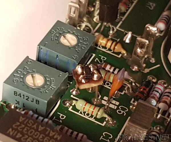
The picture above shows one of my home-brew proto board adapters with an SO-23 chip, in action on a populated and soldered PCB. In the background, a standard TO-92 transistor can be partly seen, too.
Soldering SMD (Surface Mounted Devices) chips with two, three or multiple terminals on a PCB is a hefty challenge for us oldtimers with the visual impairment and the shaky hands - but we give as good as we get, and we accept the dare!
Replacing an IC in the standard DIL (Dual-In-Line) package by its tiny SMD equivalent - just because the DIL package was considered obsolete by the manufacturers and cannot be supplied anymore - is, in fact, an easy task: For the variety of 8, 14 or more pins, our friends from banggood.com (or similar) can supply adapter PCBs for little money (search term ‘SMD adapter’). Since the shipment from China takes a lot of time, it might be a good idea to purchase some of them before you actually need them.
Carefully solder your SMD chip on one of these, install ‘pins’ using either some bare wire or multi-pin headers - and voilà!
Above you can see some of these adapters - naked, as they are delivered, and after SMD chips and pins have been installed.
But how do you get yourself out of it if you have a PCB that requires a 3-terminal component in the TO-92 (or even the old-fashioned TO-18) package, but then only an SO-23 SMD device is available?
In connection with a recent electronics project I stumbled across this exact problem: The BOM asked for a LM4041DIZ-ADJ reference voltage source in the TO-92 package, and the PCB was designed for its footprint as well. However, my usual purveyor to the house and the court did not stock it, but only had the LM4041CIM3-ADJ available, i.e., the SMD version in the teenie-weenie SO-23 package.
What to do? spake Zeus.
Above, btw, is a comparison of a TO-92 package next to an SO-23 package - and an Euro Cent as a token of scale.
I didn’t want to mess around with the (very nicely made) PCB. So I tried to produce a kind of adapter PCB from a leftover piece of prototyping board.
BTW, I don’t remember having seen any ‘design’ of a 2x2 proto board before (which is, in fact, a square of about 5x5mm).
And, in my opinion, this is the smallest sensible size for a proto board. Smaller ones, i.e. 2x1 or 1x1, with two solder pads or even only one, might be thought of. But these are neither particularly useful nor do they make any sense.
In order to check whether it is at all possible to place an SO-23 chip correctly on my piece of proto board, I first produced a drawing blown-up to 1000% (fig. 1), proving that my idea might work. BTW: If you want to do a similar thing yourself, you can easily find the dimensions of SMD components in the corresponding data sheets from the manufacturers.”