
“Measure the magnitude and direction of Earth’s magnetic field with the HMC5883L 3-axis magnetometer.
Introduction
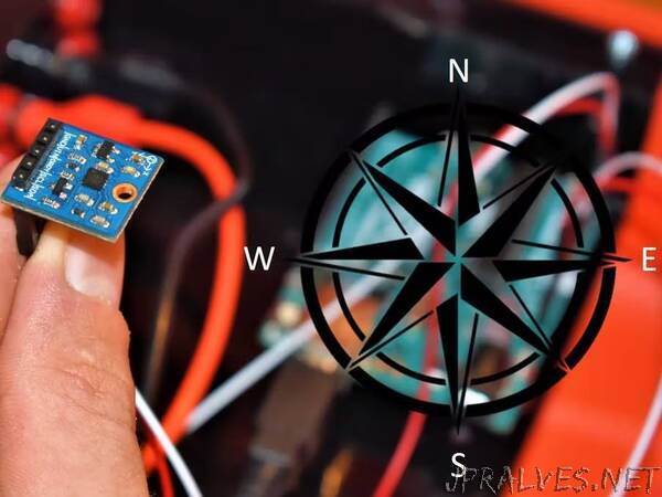
In this project, we’ll be interfacing the HMC5883L 3-axis magnetometer to an Arduino Uno. This device can measure the magnitude and direction of the Earth’s magnetic field. It’s a low-power device and can be found in mobile phones or navigation systems to provide an accurate compass heading. You can also use them to detect ferrous (contains iron) metals since the iron within the metal changes the magnetic field when it’s in close proximity to the sensor.
Don’t get lost out there, let’s get started!
20x4 Character LCD
The 20x4 LCD adds two extra rows and four extra columns per row compared to the 16x2 LCD. Similar to the 16x2 that we’ve used in previous projects, the 20x4 LCD uses the Hitachi controller so the commands and interfaces are the same. It also has the same 16-pin header, allowing you to unplug the 16x2 LCD and plug in the 20x4 without changing any wiring. The only thing we have to change is one line of code, lcd.begin(20, 4), which specifies the columns (first argument) and rows (second argument) of the LCD. An image of the 20x4 LCD is shown below.
HMC5883L 3-Axis Magnetometer
The HMC5883L 3-axis magnetometer can accurately measure the magnitude and direction of the Earth’s magnetic field in the x, y, and z direction. As a result, it can be used to provide a compass heading which is why it is also referred to as a digital compass. It is a low-powered device in a small form factor, allowing you to embed it in just about any project that requires a compass heading. A table is provided below that gives some specifications about the module.
The breakout board from Although the datasheet for the HMC5883L IC consists of 5 pins: GND, VIN, DRDY, SCL, and SDA (image shown below). The GND and VIN pins are used to power the device. Although Parallax’s datasheet says that the module can operate from 2.7V to 6.5V, we had trouble getting the magnetometer to work at 5V and thus, we recommend using 3.3Vdc. The GND and VIN pins will connect to GND and 3.3V pins on the Uno, respectively.
To communicate with the device, we use the I2C protocol which only uses two pins, SCL and SDA. We use this to configure the registers on the device (i.e., setting the measurement mode and output rate), and acquire the X, Y, and Z magnetic field measurements. The device can only be 7-bit addressed at 0x1E, so you cannot have more than one of these devices on the I2C bus at one time. The SCL and SDA pins will connect to the Uno analog pins A5 and A4, respectively.
The DRDY (data ready) pin is used to tell the master device (Uno) that data is ready in the X, Y, and Z registers. The maximum output rate is 75Hz, but by using the DRDY pin, you can achieve up to 160Hz. You can connect this pin to an interrupt pin on the Uno for an efficient way to obtain the data. However, we will not be using this DRDY pin in this project.
This device has a magneto-resistive sensor on each of its 3 axes to measure the magnetic fields. In the presence of a magnetic field, the resistance of these elements changes which causes a change in voltage across the outputs. This change in voltage is measured on each axis by the device’s 12-bit ADC and then the measurement is written to the corresponding X, Y, and Z 8-bit data registers.
An address map of each register is shown in the table below. The registers highlighted in yellow indicate the register we will be reading from to obtain the measurements of the magnetic field on each axis. To learn more about the details of each register, please consult the datasheet for the HMC5883L IC.”