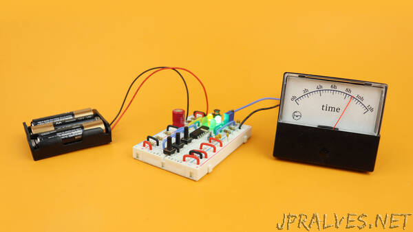
“Microcontrollers are digital devices, but in this project we will turn it around and use a PIC microcontroller to build an analog clock using a panel meter. And what’s more, we will make use of the SLEEP mode of the PIC microcontroller so that this circuit can be run off of batteries and keep the time for decades when not powered on.
The panel meter shows the time, here from 0 to 12, and a yellow LED on the breadboard tells us whether it is PM or not. The three pushbuttons on the breadboard are used like this:
ON/OFF: The leftmost button turns the clock off or on. When it is off it still keeps the time, though, because the microcontroller goes into an ultra-low power mode that is also called sleep mode, and we will talk much more about it later.
UP: Pushing the middle button increases the time.
DOWN: And yes, you guessed it, pressing the rightmost button decreases the time.
And in the rest of this article we will go through everything in much more detail: what components you need if you want to build this clock by yourself, how to program the microcontroller, and in the end I will also show you how I converted this from a breadboard project into a real-life clock that definitely gives off some Ghostbusters vibes. Let’s go!
As always, let’s first go through the components that are needed for this project:
- The brain of our clock is the PIC16F1455 microcontroller. It drives the panel meter, the LEDs, and reads out the pushbuttons.
- The panel meter (here I use a 30V version) is used as the display. You can use almost any panel meter for this project, but it needs to be modified a little bit, and we talk about it in a lot of detail below.
- All of this runs off of batteries, and besides them you also need some LEDs, some capacitors, resistors, pushbuttons, and of course a breadboard.
- The time information is generated with a 32.768kHz watch crystal, and we use a ready-made DC/DC converter module to convert the battery voltage into a stable 5V.”
