
“A difficult code with a try to display waveform on a small screen with precisions. Volts-time, frequency, duty cycle and divisions.
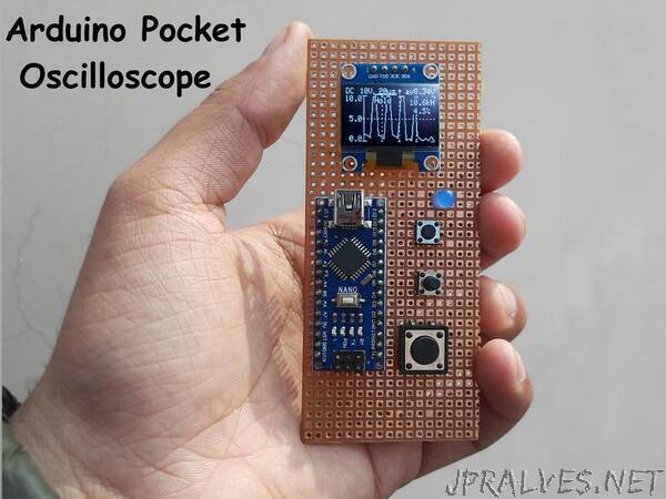
Previously, I posted a tutorial on Raspberry Pi-Pico Oscilloscope. And that was a great success. Keeping portable options in mind, I found this pretty mini oscilloscope between thousands of pages of a Japanese website. We are using a mini-OLED 128X64 to display the signal waveform, Frequency, duty cycle. 4 tactile buttons are used to change the modes, Volts/Divisions, and time/Divisions. So, I tried this, and the results are here.
Note* This project is only for educational purposes and shows the capabilities of a 16Mhz 8-bit microcontroller board. This MCU Can support frequencies below 50KHz, so it can’t be applicable for commercial and professional uses. That way, the project can also be entitled POOR MAN OSCILLOSCOPE for me.
Arduino Nano/Uno:
Both the boards have the same 8-bit Atmega328p microcontroller to use any of them. This tutorial uses I2C communication to print the readings on an OLED display. Our microcontroller has 6-channel 10-bit ADC, 13 digital I/O pins, and an 8Mhz internal clock.
Features:
- Single-channel -20Khz bandwidth
- Onscreen- Volt/Div and Time/Div
- Duty cycle monitoring
- Small 0.96-inch I2C
- AC/DC measurements option
- Mode changing, Hold state features
- Low battery consumption
- Portable and pocket-sized”