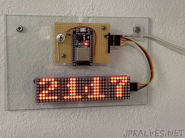
“When my very old analog wall clock stopped working, I wanted to quickly buy a new digital one, but then —- a 8x8 LED Matrix board with four modules, laying on my desk for a while, caught my attention —- and this should become a new little project. I thought about very minimal number of components, a few lines of micro-python code……… interested, you are invited to read on.
Specifications first:
- Time should be internet synchronized
- As we get UTC from the internet, correction for local time zone is required
- As LEDs can be very bright, a brightness control is needed
- Idea: wouldn’t it be nice to have an ambient light dependent automatic brightness control?
- A switch to cater for daylight savings time change
- A real time clock to operate independent for some time and reduce internet traffic
Matching these specifications with my electronic component stock on hand, I took an ESP32 node MCU board, a light dependent resistor (LDR) and the LED Matrix board with max7219 controller chips to build what I call the “Dclock”.
The ESP32 has an internal real time clock (RTC), which is used for the Dclock, but the RTC is not very accurate. With synchronization of the RTC with the internet time two times a day, accuracy is within 1 to 3 seconds late - good enough I think. If you need to sync more often, this can be set up in the dclock software, see Step 3.
There are only 5 components needed, plus a breadboard to build the Dclock.
an ESP32 node MCU board (each ESP32 based Board with enough GPIO pins should actually be OK for this project and ESP8266 based boards, with some modifications in HW and SW, see Step3)
the 4x 8 by 8 LED Matrix board with max7219 controllers
a toggle switch
a LDR-05 light dependent resistor
a 10kOhm resistor
Well, I always like to filter the supply voltage, so lets add
a 10uF electrolyte or tantalum capacitor (alternatively a 1uF capacitor will do as well)
and a 100nF ceramic capacitor
All these parts are available on the web stores of the big internet sellers and the IoT stores.”
