
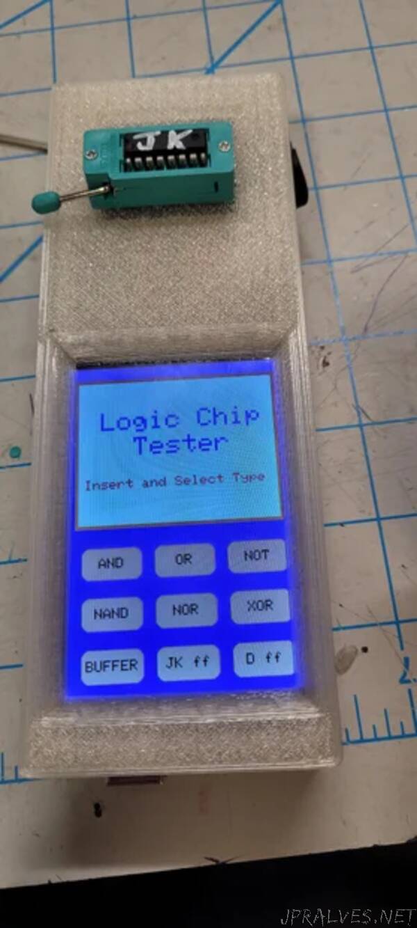
“This is a logic chip tester for the 7400 series of logic chips, covering the AND, OR, NOT, NAND, NOR, XOR, BUFFER, JK ff, and D ff. This was a project started by Dr. Tim Frank of Glendale Community College. The actual program is a product of Dr. Frank and two other students (Stephen Bakle and Noel Rojas), with the Dr. Frank being the main programmer. Dr. Frank also designed the circuit board labeled “Socket Board” using Eagle CAD. With his permission both the code and the artwork for the board are being published and included in this Instructable. Before I transferred to ASU I was asked to help develop a case for the chip tester due to my experience in modeling software and the case has evolved several times. While at ASU I continued to work on the case for the project continued to improve and change shape with using Fusion 360. As a mechanical engineering student I must give the warning that I know very little on Logic, but I can defiantly assemble and design some circuits.
Parts:
3D printed parts:
- X1, Case Top
- X1, Case Bottom
- X1, Battery compartment separator
- X1, Battery cover
- X2, Battery cover tabs
Purchased Parts:
- X1, 16 pin ZIF socket
- X1, 5.5mm Barrel Plug DC female 3 pin (comes in sets with waterproof caps)
- X1, 9 Volt battery connector
- X1, 20A 12V DC Round Toggle LED switch (also sold as rocker switch and usually advertised as car and truck switches on Amazon)
- X1, Right Angle 16 position header
- X1, IDC Box Header 16pin Male Header
- X2, 16pin Female Header IDC (it may take several if cable is miss cut.)
- X1, Rainbow Color Flat Ribbon Cable 16 conductors (I would suggest having at least a 12-inches for mistakes happen.)
- X1, Kuman 3.5-inch TFT Touch Screen for Arduino
- X2, Jumper wires (molded ends and at least 5 ½ inches in length)
- X2, 5-inch sections of 26-gauge wire (two different colors for each wire will help with color coding)
- X1, ELEGOO MEGA (or comparable board from other brands or Arduino
- X3, M3 heat set nuts (P-6075-3BR038 used can be found on McMaster as 94180A331)
- X1, M3 Countersunk 4mm
- X2, M3 Button Head 6mm
Consumables
- Heat shrink (assorted sizes)
- Super Glue
- Solder
Custom Order/made
- X1, Socket Board (files are with the Instructable (https://jlcpcb.com/) was used to make the board used)
Tools:
Needed (don’t Forget Safety Glasses)
- Soldering Iron
- Flush Cutters
- Pliers
- Scissors
- Craft knife
- Precision Pick and Probe Set
- Wire Strippers
- Lighter
- Pin Vise (with assorted bits)
- 3D printer
Highly Suggested but not necessary
- Heat set tip for soldering iron (to insert the M3 inserts)
- Wooden block with holes
- Solder Sucker
- Deburr tool
- Tapered Reamers
- Multimeter to check connections
- IDC crimper (this makes the ribbon cable a hundred percent easier to do)”