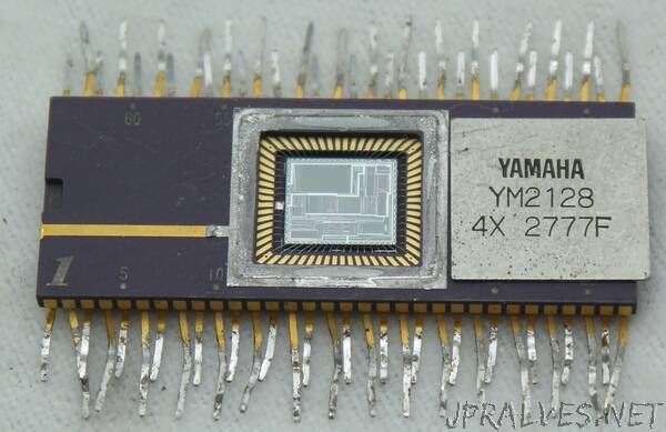
“The Yamaha DX7 digital synthesizer was released in 1983 and became “one of the most important advances in the history of modern popular music”1. It defined the sound of 1980s pop music, used by bands from A-ha and Michael Jackson to Dolly Parton and Whitney Houston. The DX7’s electric piano sound can be heard in over 40% of 1986’s top hits.2 Compared to earlier synthesizers, the DX7 was compact, inexpensive, easy to use, and provided a new soundscape.3
While digital synthesis is straightforward nowadays, microprocessors4 weren’t fast enough to do this in the early 1980s. Instead, the DX7 used two custom chips: the YM21290 EGS “envelope” chip generated frequency and envelope data, which it fed to the YM212805 OPS “operator” chip that generated the sound waveforms. In this blog post, I investigate the operator chip and how it digitally produced sounds using a technique called FM synthesis.6 21
I created the high-resolution die photo below by compositing over a hundred microscope photos.6 Around the edges, you can see the 64 bond wires attached to pads; these connect the silicon die to the chip’s 64 pins. The chip has one layer of metal, visible as the whitish lines on top. (Power and ground are the thick metal lines.) Underneath the metal, the polysilicon wiring layer appears reddish or greenish. Finally, the underlying silicon is grayish. The overall layout of the chip is dense rectangles of circuitry with the space between them used for signal routing. I will discuss these circuitry blocks in detail below.”
