
“The quartz oscillator is an important electronic circuit, providing highly-accurate timing signals at a low cost. A quartz crystal has the special property of piezoelectricity, changing its electrical properties as it vibrates. Since a crystal can be cut to vibrate at a very precise frequency, quartz oscillators are useful for many applications. Quartz oscillators were introduced in the 1920s and provided accurate frequencies for radio stations. Wristwatches were revolutionized in the 1970s by the use of highly-accurate quartz oscillators. Computers use quartz oscillators to generate their clock signals, from ENIAC in the 1940s to modern computers.1
A quartz crystal requires additional circuitry to make it oscillate, and this analog circuitry can be tricky to design. In the 1970s, crystal oscillator modules became popular, combining the quartz crystal, an integrated circuit, and discrete components into a compact, easy-to-use module. Curious about the contents of these modules, I opened one up and reverse-engineered the chip inside. In this blog post, I discuss how the module works and examine the tiny CMOS integrated circuit that runs the oscillator. There’s more happening in the module than I expected, so I hope you find it interesting.
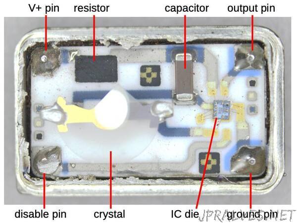
The oscillator module
I examined the oscillator module from an IBM PC card.2 The module is packaged in a rectangular 4-pin metal can that protects the circuitry from electrical noise. (It is the “Rasco Plus” rectangular can on the right, not the square IBM integrated circuit.) This module produced a 4.7174 MHz clock signal, as indicated by the text on the package.”