
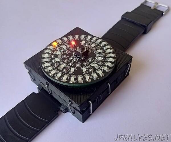
“Recently I had thought of making a DIY wrist watch but didnt worked upon it until now. What interesting about this wrist watch is that it is digital but actually analog, what I mean to say is time will be shown by LEDs but the way LEDs are arranged makes it look like more analog.
The plan is to arranged LEDs in circular format so that every number can be indicated by LEDs, to keep it simple only hours and minutes will be shown and not seconds.
So, 12 for hour and 30 for minutes (I will address this in a while) having 42 LEDs on a circular area of diameter 45mm is not a joke and and even 3mm LEDs cannot fit, many smaller SMD package are available but I decided to go with 1206 package as these can be easily soldered by hand. I opted for hand soldering so that the project can be made by any other who wants with minimal tools and materials. For soldering SMD components you have to buy solder paste, a hot air gun or hot plate iron which simply increases the cost to project
How are we going to drive 42 LEDs ?? Answer is a method called charlieplexing. Using this we can drive many LEDs with fewer pins of a microcontroller. I wont go in deep the basis is that we arrange all LEDs in matrix and then drive them by turning high one pin, low other pin and remaining in high impedance mode meaning no current flow through them. (more detail here)
If we had n number of pins we can drive n*(n-1) LEDs so for 12 LEDs of hours we need 4 pins and for 30 LEDs of minutes we need 6 pins.
The reason we have 30 LEDs for minutes is space, 60 LEDs of package 1206 just don’t fit inside area of diameter 45cm none the less time will be rounded off but still can be perceived.
I have decided to go with red and yellow LEDs as they have lower forward voltage than other colors.
According to ohms laws appropriate resistor value for red and yellow led comes out to be 150 ohm R=(Vcc - vf)/iled where vf is forward voltage of led and iled is current drawn by that that led but current while driving one LEDs goes through two microcontroller pins, in from one and out from other so actually 300ohm resistor is in series with a led when driven.
To drive LEDs we need a microcontroller and the best choice is atmega328p but the package in which it is available is not easy to hand solder so I am going to use Arduino pro mini as brain and DS1302 RTC module and Lipo battery for power and tp4056 charging module which also has overcharge and overdischarge protection.
The advantage of using atmega328 based board is that we can have any pin in high impedance mode by putting it in input mode and which is we want for charlieplexing we could have used hardcore electronics but then we need a complete understanding of it which makes the build complex so will go with microcontroller.
No special reason for choosing ds1302 module just its small size.
First layer of PCB is full with LEDs and current limiting resistors so the remaining three modules will be placed under the led PCB on another PCB and lipo battery under it and the two PCBs will not be solder but attached using headers and to make them not slip out, holes for headers will be slightly off set so that they stay in tact thanks to friction (this is small feature, we can call it plug and play).
To get time we will have a button which when pressed will trigger external interrupt and time will be shown.”