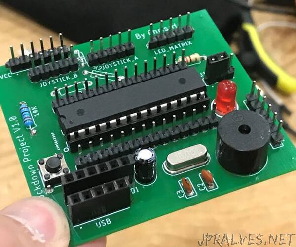
“This Instructable follows on from my ‘Pong Tennis With LED Matrix, Arduino and Joysticks’ project where we completed the wiring for the project and wrote the code. It can be found here. Or by searching Instructables for “Pong Tennis With LED Matrix, Arduino and Joysticks”.
The project is intended for everyone from beginners up however this Instructable targets those who want to take the previous pong project to the next level and put it on a custom made PCB.
To design the circuit board you first need to draw a schematic of your design on a piece of EDA (Electronic Design Automation) software, I’m using Autodesk Eagle as part of Fusion 360, a popular CAD software. I choose to use Autodesk Eagle as I was already familiar with other Autodesk software and was following the excellent Instructables Class on PCB design which can be found here.
I downloaded it from the Autodesk website here as part of the fusion 360 package.
Drawing a schematic is an easy process which involves finding the components you need in the components library, placing them on the page and then making the correct connections. This process is greatly simplified if you have a schematic to work from before drawing it out on the computer. I will be using the wiring diagram from my previous Instructable shown above.
As you can see in the second image you use the green wires to connect the components placed from the parts menu together. I have also added headers for the Arduino connections, Power and Ground so I have connections for future upgrades. Soldering headers onto these connections is optional.”
