
“This quinary ( base 5 ) LED clock project has taken me many more months than I thought it would. I spent a great deal of time considering and ruminating over exactly how I wanted it to look and operate. It’s gone through many, many, many iterations but is finally in a ‘done’ enough state that I feel quite happy with it and ready to write about it and possibly move on to other things in my life.
It began first with the concept of utilizing addressable ws2812b LED strips to indicate the time in an alternate base. I’ve worked on binary clocks a few times in the past but have grown a little tired of the concept, and I wanted to create something that would make more efficient use of fewer LEDs so that I could power them directly from an esp8266 without worrying about drawing too much power from the board itself and burning it out. I like the simplicity of not providing additional current, and I wanted to see how much utility I could sneak out of these power limitations.
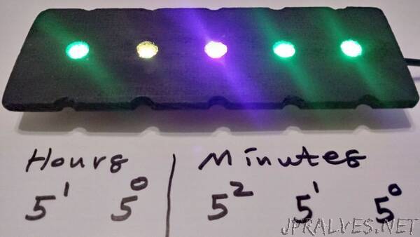
I also spent at least a few weeks determining what base to use. I was thinking about base 3, and base 8 for most of that time. What finally drew me to base 5 was when I started calculating out how many LEDs it would take to convey the number 24 ( For max hours in military time ). It takes exactly 2 LEDs to do this which I found to be perfectly succinct. Then, after realizing that 3 additional LEDs would easily allow me to show every minute value up to 59 it seemed strikingly elegant that the number of LEDs required to display both the hours and minutes ( 5 total ) was the same as the base I was using. This part of the project strangely seemed to design itself. It just felt right for the clock to be configured in this way. The more I thought about it, the more I realized that it was something I had to bring into existence as a functional art piece.
The next step was determining what colors should indicate the digits 4 through 0. What made the most sense to me was to use at least Red Green and Blue in that order. With Red being the most significant value of 4, Green being 3, and Blue as 2. I still needed to choose a value for 1, and since I like the color Purple I decided to go with that. The biggest challenge of choosing the digit colors was what to do with the digit 0. One option is to leave the LED off to indicate 0’s, but in my experience with my binary clocks, I’ve found that having at least some amount of light on this digit can be very useful for reading these sorts of displays in the dark. I originally went with the color Orange, because I liked that the first letter of the color looked like the digit it represents. Although, in practice with the particular LED strips I have, I found it more easily discernible to use a dim Yellow for 0’s. So the way I think about the final colorset is as RGBPY, or Red, Green, Blue, Purple, Yellow. The clock made a lot more sense to me after I committed these color/digit pairs to memory and I can now readily associate the colors I chose with the digit values that they represent.
The coding of this project is the part that took the least amount of time. I was able to re-use much of the code that I have used for previous esp8266 projects, although I did spend a couple of nights after work to make the code cleaner by moving certain parts of it to self-contained helper functions. The time setting portion is handled automatically using Network Time Protocol, so the esp8266 hops onto my local WIFI router and retrieves the current local time from the internet. It also syncs up with the NTP server regularly so that there isn’t much drift. I wrote a helper function to account for daylight savings time, so that unlike with my other clock projects, I won’t have to reflash the code twice a year for it to remain accurate. The settings for timezone, daylight savings time, the colorset, and everything else are defined in adjustable values up near the top of the code so that they can be adjusted easily by someone else ( Or more likely, me years from now ).”