
“We can use this notice boards at public places such as railway stations, bus terminus and inside buses for place indicators and in shops.
INTRODUCTION:
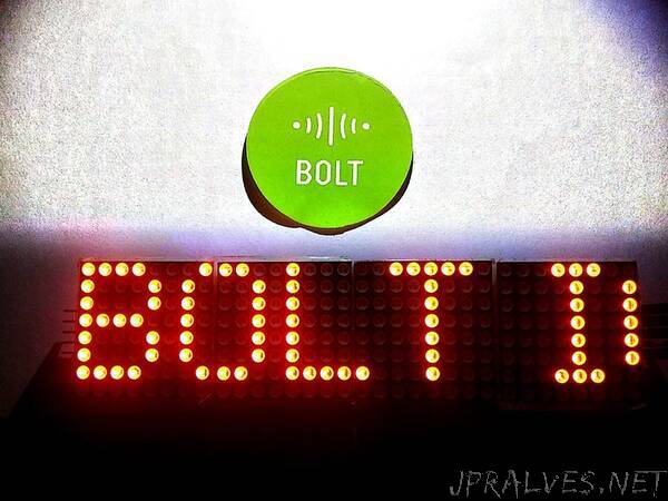
The main objective of the project is to control the notice board by using wireless communication devices like Wi-Fi module.
MATERIALS REQUIRED:
Arduino UNO, Bolt Wifi module, 8*32 LED MAX7219 matrix, Jumper wires.
METHODOLOGY:
All the connections are made by using circuit diagram. Each MAX driver can handle a 64 LEDs matrix. The arduino will send the data using a serial port communication. Connect the load pins from the arduino to all max drivers. The data pin will be only connected to the first driver from the data out pin connect the next driver and so on. Thus four 8 by 8 is connected in series. Bolt Wifi module’s Rx and Tx are connected to the Tx and Rx pins of arduino respectively and supply of 3.3 V to it and each of all max drivers. Now the code for the process is dumped in arduino by using arduino application via port b cables. To send text to the LED matrix establish a html connection with pc and arduino.The 32*8 LED matrix is also powered up by the arduino.Take in hands the BOLT Wifi module device’s id and it’s API key for login credentials.”