
“Ever since I started building projects with Arduino and the ESP8266 I have been obsessed with Home Automation and its ability to potentially make life easier and save energy and consequently money. This has been represented in my past published Instructables (See References) and so a challenge was born when I discovered that the geyser in my new home roof space was connected to the mains power 24/7 with no local on/off control and was controlled by a relatively inaccurate internal thermostat not to mention the difficulty to adjust the water temperature setting. The task - how to bring the water temperature control easily to me with an ability to display/record the temperature/power consumption trends over the last 24 hours to allow me to maximise my water temperature when I needed it at the lowest possible power consumption.
Main features of the controller include:
Water temperature measurement and display
Up to 4 extra optional sensors that can be attached to the external skin of the geyser to monitor the geyser external temperatures - used to assess the need for any external geyser insulation. After this exercise is done, you may if you prefer remove the sensors or simply leave them in place to monitor and log the geyser wall temperatures with the water temperature for reference. The firmware auto adapts to the number of sensors connected to it.
Two timed controller periods, each with its own start/stop times and separate ON/OFF setpoint values.
Automatic logging every hour of the average water temperature over the last hour, each external skin sensor plus the number of minutes that the geyser has been ON during the last hour.
All of the above can be viewed on the optional local OLED display.
A “display sleep” timer that switches the display off and on at a specified time over the 24 hour period to prevent possible light noise in the room.
A control button to step through the various screen displays or “wake” up the display for a short duration if it is in sleep mode
Additionally all of the above real time and logged data plus all configuration is available online via your computer or mobile phone using a series of web pages on your browser connected directly to your home WiFi network and/or in the absence of a local connection you can start the Controllers own WiFi Access point and connect to that and then use it identically as per the home network connection.
A high water temperature check that switches the geyser OFF if the water temperature exceeds 75’C
Error messages in the event of sensor fail or open circuit.
The controller clock runs either directly from an optional real time clock that itself is maintained automatically from an online NTP time server. If the RTC is not fitted, the internal software clock is maintained using the NTP time server.
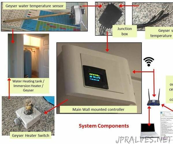
A block diagram of the complete Geyser Control System (GCS) can be seen in the above figure.
It physically comprises the following parts, each described further in the project
The Geyser temperature measurement probe constructed from a modified geyser thermostat compatible with the geyser (Either modify the one currently in place or purchase a new one from the plumbing supplies shop).
Up to four optional geyser “skin” or wall temperature sensors that can be attached to the wall of the geyser to measure the outside temperature of the geyser.
A junction box to connect up to 5 temperature sensors into one 3 wire bus connection to the controller.
A solid state relay (SSR) switching module to be used for the remote switching of the geyser heater from the main control unit. For safety, this is housed in its own housing complete with a heat sink. (Note. My photo shows an earlier prototype using a normal relay, actual installed unit uses the SSR)
The main control unit with a single control button and optional small OLED display for the local display of all main measurements, logged data and settings. An integrated web server & browser screens are available to read and set up the controller (The display is optional simply because the whole interface of the controller can be handled via its WiFi connection)”