
“Shopping for family is a struggle for me around Christmas. I’m not the best at presents to begin with let alone finding something interesting they don’t already have. So, this year I decided to make my presents. This won’t be my first time doing this however last year didn’t really go as planned…. But that’s a story for another time.
Before I delve into the ins and outs of the project, a tiny bit of background on me. I am a 2nd year Electronic Engineering student in the UK. I have recently started turning my room into electronics lab so I thought I would put it to use. Now onto the project!
Around November I saw a Reddit post of a Simon Says game someone had made. It was Arduino based and presented in a cardboard box (sorry I haven’t got a link) . I thought It looked like a fun project and the perfect little game that I could give as a Christmas present to my family. The first thing I decided I wanted to do was to turn this into PCB based game powered with a coin cell, this allowed it to be compact, portable and help me improve my PCB design skills. The second thing was to use an ATTINY85, looking back on it I don’t know why I choose to go with the ATTINY85 straight away, but it seemed to call to me. That and I wanted to try something different from the Arduinos I have been using.
To keep everyone on the same page on I mean by Simon Says game, for me Simon Says is childhood memories where “Simon” will say “Simon Says Touch your feet” and you do it. This carries on with random actions until they say something like “Jump up and down” those who it lose as Simon didn’t say it. The game I am making is a bit different but in the same vain. The basic idea is some LEDs will flash in a random order and the user repeats the sequence back at with a button related to each LED. I decided to go for 4 LED each a different colour because that is what the project I saw on Reddit did. I plan on having different levels you play though. First level will be 4 colours you have to remember, second level will have 5 etc until you get the combination wrong. Then it will start all over again.
I started designing the game and ran into my first problem very quickly. The game I outlined above requires four outputs for the LEDs and 4 inputs for the buttons. This is a small issue as the ATTINY85 I’m using only has five I/O pins, six if you are being cheeky with the reset pin. To google I went and after some time I came across the solution of using a voltage divider chain and the built in ADC, but I felt like I could do better. Back to the drawing to see if I could come up with anything better and no dice. Now to google again and this time I had more luck. An electronics stack exchange post that lets you use one I/O pin to control an LED and read a button input. Score! However, you can’t do both at the same time but that is no issue for this project. The only downside mentioned is when the button is pressed the LED lights up… which happens to be a big upside for me. I wanted the LED for that button to light up anyway to show it has been inputted, so that has saved me some programming. Great so we have an idea and a basic schematic so, let’s start prototyping.
Above you can see the setup I used for prototyping. LEDs are controlled by using the microcontroller as a current sink. The positive side of the LED is connected to a current limiting resistor which is connected to the power supply. The negative side of the LED is connected to a pin of the microcontroller. To turn the LED on the microcontroller just has to pull that in low. This allows the microcontroller to sink current, completing the circuit and lighting up the LED. The buttons work by one side being connected to the negative side of the LED and the other to ground. To see if a button has been pressed the microcontroller sets the pin to an input making it high impedance and measures the voltage on that pin. When the button isn’t pressed the pin will be floating and when pressed it will be at ground, 0V. I now had control of the LEDs and buttons and all is good. Looking back on this I can see the error of my way of my ways leaving the pin floating, but I will get to that later. So now it was time to test it on the ATTINY85, unfortunately I didn’t have any on had. Luckily for me, the lovely people at Microchip provide free samples for students like me, so I requested three ATTINY8585s. While I waited for them to arrive, I started programming the game on my Arduino Uno which was a fairly basic affair and I’m defiantly not a programmer. The code itself was a bit ruff, well it still is, but worked well enough. I will upload the end result to GitHub but it’s quite different to how it began and went through many, many iterations. I need to remember to start with GitHub next time, version control would of helped a lot.
And they have arrived, three ATTINY85s! Nothing is better than free microcontrollers. I have never used an ATTINY85 before so after a quick google I found a guide on how to use the Arduino as an In System Programmer (ISP). After downloading the Ardunio-tiny library and setting it all up… It didn’t work and I had no idea why. More googling later and I hadn’t burnt the bootloader, think I read through the tutorial a bit too quickly. Now it was working, and the game was running great on the ATTINY85. I changed the input voltage from the 5V I normal use the 3V that the battery uses for some testing… and nothing worked, I was getting random triggers of the buttons and they weren’t working when I pressed them. Then it occurred to me, due the lower supply voltage, the threshold for a low level is now lower causing the floating pin to trigger more easily. This causes me to panic and try different circuits and even ask the internet. I posted on electronics stack exchange and someone mention enabling the internal pull-ups, turning these on would mean that the voltage on the negative side of the LEDs would be high at the supply voltage and I could still use the button input. I felt a bit dumb at that moment but relieved I didn’t have to change my circuit, only just a bit of code.
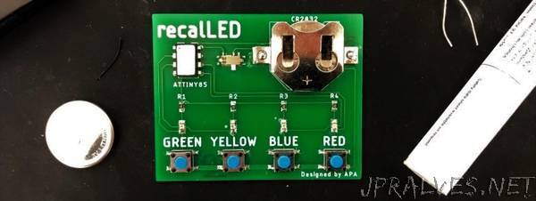
Now I have the ATTINY85 working with the game on it and a schematic, I started to put the PCB together. For this I used Eagle by Autodesk, mainly because it is what my Uni uses, but I do like and prefer it to KiCAD which is the only other one I have tried. This was quite simple as the there was less than 30 components and mostly the same few repeated four times. To pick the components I just went on Farrell and used the parametric search to narrow down the choices and then filter the results to find the cheapest. Once everything was selected, I put them into Eagle and made any footprints I didn’t have. I decided to go for surface mount as it find it neater and more compact. This turned out to a mistake which I will go into later. Once I have finalized the design, I sent it off to my PCB Manufacture of choice. Now I had wait for the cheapest shipping option, which takes about 2 weeks to get here.”