
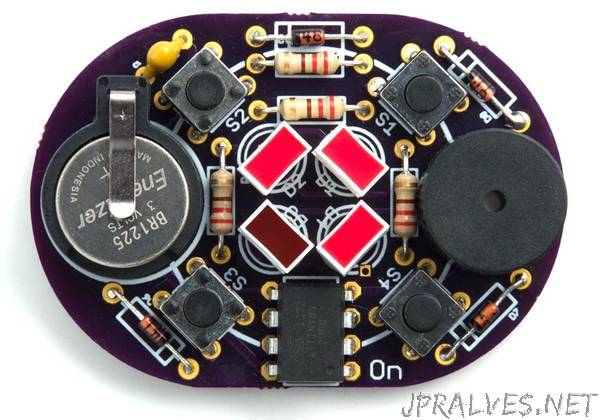
“Since publishing my Secret Maze project I’ve designed a printed circuit board for the circuit, to make it easier to build a convenient pocket version of the game:
To avoid the need for an on/off switch I’ve updated the program to automatically go to sleep if there has been no keypress for 30 seconds; this has the advantage that it’s not possible to inadvertently leave the game on, and run down the battery. To wake up the game you press the button labelled On on the PCB. The power consumption in sleep mode is about 0.25µA at 3V, which is negligible.
There’s a link to the Eagle files at the end of the article if you want to make yourself a board.
The printed circuit board is designed for through-hole components, so it should be suitable for people without much soldering experience. I made it as compact as possible, with the pushbuttons arranged in a diamond shape; this doesn’t affect the maze as long as you make sure you hold the board in a consistent orientation.
I recommend using the ATtiny85V variant of the processor as this is rated down to 1.8V, so it will extend the life as the battery fades. The circuit powered by a 12mm 3V coin cell; types CR1216, CR1220, or CR1225 are suitable. The battery fits in a through-hole 12mm coin cell holder [2].
The board is designed for standard 5mm LEDs, but will also accommodate single-bar LEDs [3] which give a nice visual representation of the four walls of the maze. I recommend using red LEDs, as these are the brightest when powered fom a 3V battery. The buzzer is a 12mm (0.5”) diameter piezo buzzer.
I programmed the ATtiny85 after I had soldered it onto the circuit board by piggy-backing an 8-pin IC socket on top of it, and then plugged in the wires from my Tiny AVR Programmer board. Alternatively you could program the ATtiny85 in the socket on the Tiny AVR Programmer board before soldering it in, or use an IC socket.”