
“See how I have made my own PCB for the well-known ATtiny85 Arcade game circuit. Here you will have the schematic, parts list, step by step of soldering components, how to burn bootloader and how to upload codes for different games to the ATtiny85.
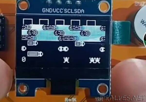
The connections are very easy. The ATtiny has 6 pins taht we could use and a supply of 3V from the battery and GND pin. Don’t worry, the chip works fine at 3V and the same for the rest of the components. The buttons have a pulldown and are conencted to pins PB0, 2 and 5. The OLED display needs i2c communication and that is created on pins PB4 and PB3 for data and clock. We have the SPI port for ISP programming with the Arduino.
ELECTRONIC COMPONENTS
- 1 BUZZER
- 1 PCB
- 1 PANTALLA OLED
- 1 ATTINY85
- 4 RES 1K 1206 SMD
- 1 RES 10K 1206 SMD
- 1 RES 220 ohm SMD
- 1 DIODO LED 1206 RED
- 3 BUTTON NO 2 PIN
- 1 SWICTH 6 PIN
- 1 SOCKET BATTERY CR2032
- 1 BATTERY CR2032 3VDC”