
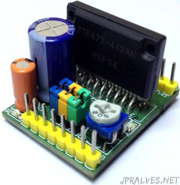
“Unipolar stepper motor driver can drive unipolar motor up to 3.5A and supply range 10 To 50V DC. The board has been designed using STK672-442AEN IC. The STK672-442AN is a hybrid IC for use as a unipolar, 2-phase stepper motor driver with PWM current control and Micro-stepping.
Features
Supply Up to 50V DC Input
Logic Supply 5V DC Input
Load Current 3.5Amps
Stepper Motor: 5 Wires, 6 Wires, 8 Wires (Unipolar)
Built-in over current detection function, over heat detection function (Output Off)
Fault 1 signal ( Active Low) is output when overcurrent or over heat is detected
Fault 2 signal is used to output the result of activation of protection circuit detection at 2 levels.
Built-in power on reset function
A Micro-step sin wave driven driver can be activated merely by inputting an external clock.
The Switch timing of the 4-phase distributor can be switched by setting an external pin (Mode3) to detect either the rise or fall, or rise only, of clock input.
The Enable pin can be used to cut output current while maintaining the excitation mode.
With a wide current setting range, power consumption can be reduced during standby.
No Motor noise during hold mode due to external excitation current control.
Incorporating a current detection resistor (0.122Ω: resistor tolerance +/-2%), motor current can be set using two external resistors.
Phase is maintained even when the excitation mode is switched. Rotational direction switching function
External pins can be used to select 2, 1-2 (including pseudo-micro), W1-2, 2 W1-2, or 4W1-2 excitation.
Clock Input : Input frequency 20Khz when using both edge, Or 50Khz when using one edge
Minimum pulse width 20us When using both edge Or 10us when using one edge
M3: Jumper J3-Open the excitation phase moves one step at a time at the rising edge of the CLOCK pulse.
M3: Jumper J3-Closed the excitation phase moves alternately one step at a time at the rising and falling edges of the CLOCK pulse.
Do not Change direction during the 7us interval before and after the rising and falling edges of CLOCK input.
Enable : Normally High for Normal Operation, Pull down control of excitation drive output A, AB, B, and BB, and selecting operation/hold status inside the HIC”