
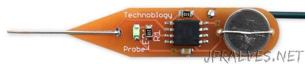
“This article describes a simple continuity tester, based on an ATtiny85 and a piezo buzzer, designed for checking circuit wiring, or tracing out the tracks on a PCB:
It has a low threshold resistance of 50Ω to avoid false positives, and passes less than 0.1mA through the circuit under test, to avoid affecting sensitive components. It’s powered from a small button cell, and automatically switches itself off when not in use, avoiding the need for an on/off switch.
Introduction
I recently designed a PCB with very fine tracks for a project I’m planning for a future article, and thought it would be useful to have a small, portable continuity tester to help check for solder bridges on the SMD soldering. Although most multimeters include a continuity tester mode, I wanted to design a stand-alone tool with the following advantages:
Smaller and more convenient than a multimeter.
Low threshold resistance of 50Ω, avoiding false positives due to other components in the circuit.
Fast response, so you can drag the probe across a line of pins to detect shorts.
Low current, to avoid affecting sensitive components in the circuit under test. This circuit passes only 100µA through the probes, which is a factor of 10 less than most multimeters.
No on/off switch, so there’s no danger of leaving it switched on and running down the battery. The circuit automatically goes to sleep if it’s unused for 60 seconds, and the standby power consumption is less than 1µA, giving a battery life of several years.
An LED shows when the circuit is switched on; this is optional, but I like having confirmation that it’s working.
At first sight, using a microcontroller for this application seems overkill; however, I think it would take quite a complex circuit of discrete components to meet all of these requirements.”