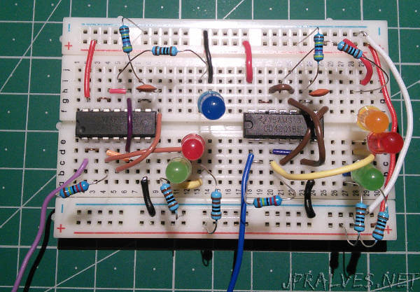
Today we will build two circuits that work as logic probes that inform us of the state of the signal under analysis through LEDs.
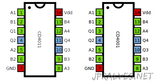
One circuit uses the IC CD4001 and the other uses the IC CD4011, the first implements 4 NOR ports with Buffer and the second one implements 4 NAND ports with buffer. Using a probe (which is connected to pin 1 of the ICs) we can check if the circuit we are seeing is in the LOW or HIGH state, or if it is switching.
In order to use this probe in a circuit, the VCC and the GND of the circuit must be connected to the Probe. Then the pin labeled “probe” can be used to analyze the circuit to be tested. The LEDs will flash according to the state of the circuit - Red in HIGH state, Green in LOW state and Yellow when the circuit is “pulsating”.
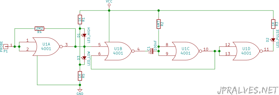
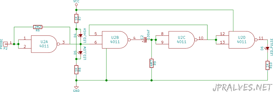
Schematic
Bill of materials (BOM)
Circuit 1:
- 1x IC CD4001 (U1)
- 1x 100nF Ceramic Capacitor (C1)
- 3x 1K Ohms Resistors (R1, R3 e R5)
- 1x 2.2M Ohms Resistor (R4)
- 1x 4.7M Ohms Resistor (R2)
- 1x 5mm red LED
- 1x 5mm green LED
- 1x 5mm yellow LED
Circuit 2:
- 1x IC CD4011 (U2)
- 1x 100nF Ceramic Capacitor (C2)
- 3x 1K Ohms Resistors (R7, R8, R10)
- 1x 2.2M Ohms Resistor (R6)
- 1x 4.7M Ohms Resistor (R9)
- 1x 5mm red LED
- 1x 5mm green LED
- 1x 5mm yellow LED
IC/Component Pin-out