
Other
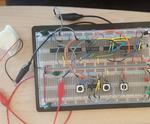
“This project demonstrates the basics of digital logic, the characteristics of a NE555 timer, and demonstrates how binary numbers are counted. The components used are: a NE555 timer, a 12-bit ripple counter, two 2-input NOR gates, a 4-input AND gate …
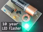
“This LED flasher circuit will run for 10 years on a single 1.5V AA cell. Circuit is basically a “gated” blocking oscillator (joule thief) . IC1 CD4001 requires 3V and will not run from 1.5V (AA cell) when first …
“Oscilloscopes are extremely helpful when you’re testing and troubleshooting digital circuits. But for many individuals, an oscilloscope may not be a solution because of the price tag (hundreds to thousands of dollars) or the bench space. The first oscilloscope …
“DC Motor Direction Control project offers direction control using digital logic gates and a DPDT relay.”
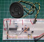
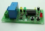
Today a circuit will be built to make a two-tone doorbell. We will use two ICs, one CD4060 which is an oscillator with a 14-step binary counter and a CD4001 that implements 4 NOR ports. The first integrated will divide …
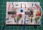
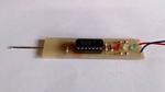
Today we will build two circuits that work as logic probes that inform us of the state of the signal under analysis through LEDs. One circuit uses the IC CD4001 and the other uses the IC CD4011, the first implements …