Content for 74HC193

74HC193

The 74HC193; 74HCT193 is a 4-bit synchronous binary up/down counter. Separate up/down clocks, CPU and CPD respectively, simplify operation. The outputs change state synchronously with the LOW-to-HIGH transition of either clock input. If the CPU clock is pulsed while CPD is held HIGH, the device will count up. If the CPD clock is pulsed while CPU is held HIGH, the device will count down. Only one clock input can be held HIGH at any time to guarantee predictable behavior. The device can be cleared at any time by the asynchronous master reset input (MR); it may also be loaded in parallel by activating the asynchronous parallel load input (PL). The terminal count up (TCU) and terminal count down (TCD) outputs are normally HIGH. When the circuit has reached the maximum count state of 15, the next HIGH-to-LOW transition of CPU will cause TCU to go LOW. TCU will stay LOW until CPU goes HIGH again, duplicating the count up clock. Likewise, the TCD output will go LOW when the circuit is in the zero state and the CPD goes LOW. The terminal count outputs can be used as the clock input signals to the next higher order circuit in a multistage counter, since they duplicate the clock waveforms. Multistage counters will not be fully synchronous, since there is a slight delay time difference added for each stage that is added. The counter may be preset by the asynchronous parallel load capability of the circuit. Information present on the parallel data inputs (D0 to D3) is loaded into the counter and appears on the outputs (Q0 to Q3) regardless of the conditions of the clock inputs when the parallel load (PL) input is LOW. A HIGH level on the master reset (MR) input will disable the parallel load gates, override both clock inputs and set all outputs (Q0 to Q3) LOW. If one of the clock inputs is LOW during and after a reset or load operation, the next LOW-to-HIGH transition of that clock will be interpreted as a legitimate signal and will be counted. Inputs include clamp diodes. This enables the use of current limiting resistors to interface inputs to voltages in excess of VCC.

MK1 8bit Computer

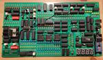
“The MK1 CPU is composed of several modules, all connected trough a common 8-bit BUS, the status of each module is shown by dedicated LEDs. The clock module is designed to allow step-by-step execution; in automatic mode the clock speed …

Transistor Radio Series - The 7 MHz Scratch Synthesizer

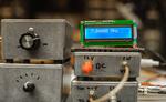
“I like making simple component-level radios. This Fall, I rekindled my love for making transistor radios and hope to slowly blog some circuits and fun. I’m warning you now — these circuits hearken the 1970s and 80s, SSD, EMRFD, old …

VXO based PLL Frequency Synthesizer for 7 MHz

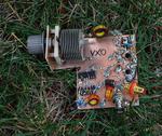
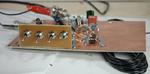
“In EMRFD, 4.10, Wes provides the schema for a versatile VXO - extending frequency synthesizer. Although, I referred him to Wes for help, a reader asked me some questions and I ended up designing some pieces for him. In order …

Frequency synthesizer for my Jupiter receiver

“Radio astronomy offers much fun + learning for the radio homebuilder — example topics include how to design and make antennas, LNAs, receivers, and frequency synthesizers from HF to microwave. Further we may craft op-amp analog integrators to remove background noise, and …