
“This project is a complete design of a high-power three-channel LED driver board, designed in KiCAD, and all the fabrication files
Introduction
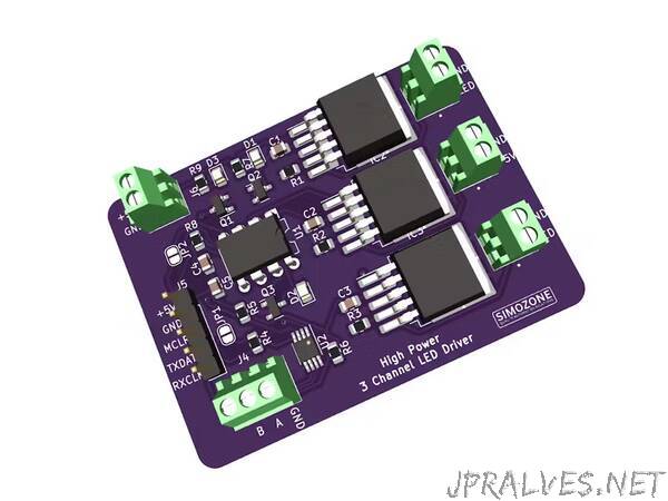
I have been thinking about how to drive RGB LED patterns most simply. In my day-to-day research, I thought of integrating various integrated circuits and associated components to build a high-power three-channel LED driver that can help me drive my LED decoration circuits. At first, this didn’t look easy, but with more research, I chose the IC that could fit my requirements. This project will highlight the electronic components that I settled for, the schematic design of the project, the 3D output of how the board will look after fabrication, and finally, how to order such a board through the PCBWay online platform. Let us dive deeper and see how the project is coming up.
Required Components
- 0.1uF Polarized capacitor, small US symbol C1, C2, C3, C4, C5 C_0805_2012Metric
- LED_Small Light emitting diode, small symbol D1, D2, D3 LED_0805_2012Metric
- CAT4101 IC1, IC2, IC3 TO-263-5_TabPin3
- Screw_Terminal_01x02 Generic screw terminal, single row, 01x02, script generated (kicad-library-utils/schlib/autogen/connector/) J1, J2, J3, J6 TE_282834-2
- Screw_Terminal_01x03 Generic screw terminal, single row, 01x03, script generated (kicad-library-utils/schlib/autogen/connector/) J4 TE_282834-3
- Conn_01x05 Generic connector, single row, 01x05, script generated (kicad-library-utils/schlib/autogen/connector/) J5 PinHeader_1x05_P2.54mm_Vertical
- Jumper_2_Open Jumper, 2-pole, open JP1 SolderJumper-2_P1.3mm_Open_RoundedPad1.0x1.5mm
- Jumper_2_Bridged Jumper, 2-pole, closed/bridged JP2 SolderJumper-2_P1.3mm_Bridged2Bar_RoundedPad1.0x1.5mm 2N7002 0.115A Id, 60V Vds, N-Channel MOSFET, SOT-23 Q1, Q2, Q3 SOT-23
- 1.4k Resistor, small US symbol R1, R2, R3 R_0805_2012Metric
- 10K Resistor, small US symbol R4, R5, R6 R_0805_2012Metric
- 511 Resistor, small US symbol R7, R8, R9 R_0805_2012Metric
- PIC12F1501-IMC PIC12F1501, 1024W FLASH, 64B SRAM, DFN8 U1 DIP-8_W7.62mm
- MAX485E Half duplex RS-485/RS-422, 2.5 Mbps, ±15kV electro-static discharge (ESD) protection, no slew-rate, no low-power shutdown, with receiver/driver enable, 32 receiver drive capacity, DIP-8 and SOIC-8 U2 MSOP-8-1EP_3x3mm_P0.65mm_EP1.68x1.88mm
PIC12F1501
The project is built around this IC. It is a microchip I used for PMW light emitting diode control and over the serial communication. The IC has multiple PMW outputs and several UART communication protocols that could fit what I wanted to achieve. With its 3.5KB program memory and 8-bit IC, the objective of driving LEDs through three channels could be easily achieved.
MAX485E
This has been incorporated to offer multiple communications within the board. It offers a half-duplex protocol communication through a two-wire by adopting the RS485 protocol, thus making the communication happen over a long range. It also brings in the ability to connect more boards to the bus.
CAT4101
This LED driver is incorporated to ensure that the LED is driven using a constant current that goes up to 1A within the control mechanism. This allows the LED to be powered ON without being overheated. In other words, it protects the LEDs against overvoltage. Its ability to integrate with the PMW control capability made me settle for it.”