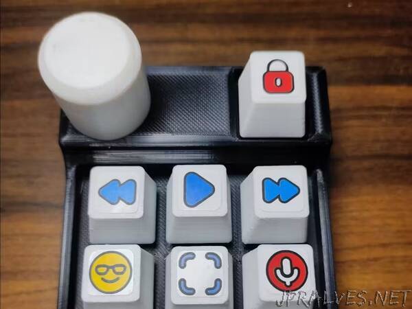
“It’s a 3D printable DIY macropad that uses an Arduino Nano (ATmega328P) and works without V-USB.
A few weeks back I was searching for a nice macropad but couldn’t find anything that justified its price. So I decided to design and build myself one. But instead of using an HID-supported chip like an ATmega32U4 which would have made things a lot easier, I decided to go with a non-HID one i.e. an ATmega328P on an Arduino Nano. It’s because what I discovered is that nobody even dares to touch this chip while building a custom macropad or a keyboard due to its lack of emulating an HID device. Although some folks have tried a way around using V-USB, but it’s very resource-consuming, slow and requires adding additional components to the board. So to save you guys all that hassle, I decided to show that it’s possible to build an HID-simulating device using an ATmega328P.
Before proceeding make sure that you have all the components and tools mentioned above. If you’re planning to make something per your requirements, go ahead. It’s all about DIY.
Hardware :
First of all, begin with printing the STL files from my Printables. Once printed attach mechanical switches and a rotary encoder to the case. Also, note that here I am using a rotary encoder w/o a breakout board due to lack of space, If you’re following along, you may want to unsolder the encoder from its breakout board.
Now we need to attach the through-hole LEDs to the switches and create a 3x3 keypad matrix and solder them all together. The LEDs should be soldered together in parallel along with a 150 Ohm resistor. If you have no clue about how a keypad matrix works, you can read this article by Dave Dribin - Keyboard Matrix Help, as explaining a keypad matrix is beyond the scope of this article. Even if you’re unable to understand the working just follow the schematic and make sure that you’re using some blocking diode. I personally used 1N4007 for this project.
Lets pick up the soldering iron one last time. This time solder all the components to the Arduino Nano. You can check the GitHub project code for the exact pin number of each component that is going to send data to the Arduino. For the LEDs, simply connect them to the Arduino’s 5V output. Now connect all the ground wires to the Arduino’s ground pin. I twisted and soldered them all in one.Finally, power the Arduino with a USB cable and see if the LEDs turn on.
Once again check all the connections with a multimeter and hot glue the Arduino to the bottom lid and close the enclosure with some super glue and attach the encoder knob. But wait, there’s something missing. Aha, the keycaps. I didn’t bother mentioning them because there are so many options available for keycaps and everyone has a personal choice. So buy or 3D print some keycaps and put them on.
Software :
To get started download the GitHub repository mentioned in this project. Open the project folder in VS Code. Also, make sure that you have Platform IO and Python installed. Head over to ArduinoProject/src/main.cpp where you can find all the pin numbers. If needed, just change them as per your wiring. If you head over to the include>Constants.h you would see a bunch of strings declared there. These are the messages that Arduino would be sending to the PC over the serial port on press of individual buttons which would then be decoded by the Python script running on the PC and converted to keystrokes. Once ready flash the code to the Arduino board and make sure you’re able to see the messages in the serial monitor.
The Python script is extremely simple to understand. It actively listens for the incoming serial port messages on the specified port and translates them into keystrokes. You can look through the code and keyboard library to change the macros as per your preference. Once ready run the script and check if your macros are working correctly. Finally, create a copy of your script and change the extension from .py to .pyw and place it here : C:\Users\username\AppData\Roaming\Microsoft\Windows\Start Menu\Programs\Startup. This would make sure that the script is up and running when the PC boots.”
