
“let’s build a PD trigger
USB has evolved from a data interface capable of supplying limited power to a primary provider of power with a data interface. Today many devices charge or get their power from USB ports contained in laptops, workstations, docking stations, displays, cars, aeroplanes or even wall sockets. USB has become a ubiquitous power socket for many small devices such as cell phones, tablets, portable speakers, and other hand-held devices. Users need aUSB to fulfil their requirements not only in terms of data but also to provide power to, or charge, their devices simply, often without the need to load a driver, in order to carry out “traditional” USB functions. The USB Power Delivery (USB PD) Specification enables the maximum functionality of USB by providing more flexible power delivery along with data over a single cable. Its aim is to operate with and build on the existing USB ecosystem. The main blocks in power delivery systems are the source and the sink. The source supplies power over VBUS when the negotiation from the sink controller is successful. The PD systems use the CC1 and CC2 lines in the USB C cable for negotiation.
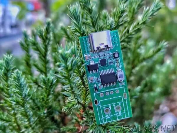
PD Trigger Modules
Power Delivery (PD) trigger modules are used to get a desired voltage ranging from 5v to 20V from a PD-compatible power supply. PD trigger modules are typically composed of aPD sink controllers with various supporting components. One such PD sink controller that is commonly used in PD trigger modules is the FUSB302. In this project, we have used the very same FUSB302 PD controller in our PD trigger module.
Components Required
- STM32F030 Microcontroller
- FUSB30 Programmable USB Type‐C Controller with PD
- 3.3V Voltage regulator
- RGB LED
- Tactile Switch
- Resistors
- Capacitors
- USB Type-C connector
- PCB
- Other tools and miscellaneous”