
“A basic 4 channel mono audio mixer with gain amplifier and a 10 LED VU-meter
BACKGROUND
I am designing and building a series of Eurorack modules for interfacing modular analog synthesizers. As I am not a musician, I am more interested in learning than in actual sound quality. Which does not mean that the designs are of poor audio quality, but you might find 12-bit analog processing and, definitively, you will not find tube valve amplifiers. You may check my other Eurorack module projects.
As these projects are really quite basic, I believe they might be a good starting point in the electronic music and audio electronics. I have found a good reference for designing some circuits for the projects in the following books:
Ray Wilson (2013) “Make: Analog Synthesizers: Make Electronic Sounds the Synth-DIY Way”, Make Media, Sebastopol CA
Nicolas Collins (2020) “Handmade Electronic Music: The Art of Hardware Hacking”, 3rd Edition, Routledge, New York
ELECTRONICS
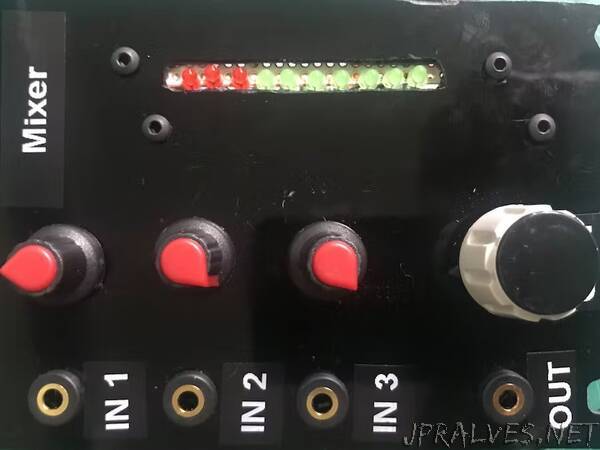
The goal of this module is merging the output from other Eurorack modules. We can modify the amplitude of each input independently, and we can also modify the output gain. A VU-meter is included so that the output level is easily monitored. One nice feature of this project is that it is modular in itself: you can easily change the design, including all or only some of the stages.
WARNING: it is recommended to use 1% tolerance resistors, because the values of some of them are required to be very close, for instance all the resistors in the mixing and gain stage.
Let’s start with the power supply. A typical Eurorack backplate supplies +12V, -12V and +5V using an IDC-16 connector. We will only use +12V and -12V, and will add some capacitors for reducing noise and ripple. C1, C9 and C10 are polarized, so check the pinout.
The mixing stage is straightforward. The potentiometers RV1, RV2, RV3 and RV4 modify the level of their corresponding inputs. The signals are then merged through 100 kOhm resistors (R1, R2, R3, and R4). You might add additional inputs following the same schema. For the prototype version I only mounted three inputs. One important note is that this circuit is AC-coupled, which is adequate for audio signals mixing. If you want instead to merge modulator signals (i.e. LFOs or the like), you have to change it to DC-coupled by just removing the AC-coupling capacitors from the mixing (C5, C6, C7 and C8) and gain (C12) stages.
The gain stage consists of a simple preamplifier with two operational amplifiers. I have used NE5532, which are low noise and are good for non-demanding audio applications. But you may use any dual opamp like the LM358. The first opamp is configured as an inverting buffer with gain of -1. The second opamp is configured as an inverting buffer with variable gain, from -0.1 to -10.1. Because of the two inverting buffers the signal is restored to its original form. The output of the gain stage can be connected to any other external module.
At this point, the module is fully functional. But I though it could be a nice feature tu include a VU-meterstage to monitor the output level of the signal using a LM3915N integrated circuit which does pretty much all the work. The input signal for this stage is the output signal of the gain stage, but it must be routed through a resistor (R12), in this case a 10 kOhm resistor is fine. The basic circuit for the VU-meter is simple. The IC manages 10 LEDs, and its them depending on the input level. I have used green (D2, D3, D4, D5, D6, D7 and D8) and red (D9, D10 and D11) LEDs, the red LEDs for the higher level values. One important thing with this IC is limiting the power combustion of the LEDs (otherwise it will get hot). The voyage divider for REFOUT and REFADJ pins is configured to limit to 17 mA each LED consumption. In addition there is a current limiter (R16 and R17) for all the LEDs configured to limit the overall consumption to 149 mA. Although in average the current flowing by the LEDs will be small, at peaks it might get high. For this reason R16 and R17 should be 1 W.
The LM3915N can be used in different configurations. One of them is using a half wave peak detector. I you prefer the default configuration (which is reasonably), you do not need to mount the peak detector. In this case just route SIG_IN directly to SIG_OUT. Otherwise, bridge the output of the gain stage (SIG_IN) to the input of the VU-meter (SIG_OUT) using the following circuit, obtained directly from the IC datasheet. If you feel like having both options, just add a switch to bypass the peak detector circuit.”