
“Utilizing the NE5532 operational amplifier, a voice level meter circuit assesses audio signals.
The NE5532 is a widely used operational amplifier (op-amp), carefully designed for applications requiring excellent audio performance. This IC is frequently used in various audio equipment, including mixers, amplifying devices, preamplifiers, and audio processors. Some of its main characteristics and abilities are provided below:
Op-Amp, or operational amplifier A dual-channel op-amp, the NE5532 contains two separate op-amp circuits in a single package. Because each op-amp maintains independent functionality, it can be used for various audio signal processing tasks.
Low Noise: The NE5532’s outstanding ability to reduce noise is one of its distinguishing features. This characteristic makes it especially suitable for audio scenarios where maintaining high signal integrity and reducing background noise are crucial.
Low Distortion: The NE5532 is essential for maintaining audio signal quality after amplification because it was designed to produce very little harmonic distortion.
NE5532 IC
The NE5532 op-amp’s 8-pin layout accommodates diverse functions. Pins 1 and 8 are power supply (V+ and V-) connectors. Pins 2, 3, 5, and 6 are input points for inverting and non-inverting signals. Pin 4 adjusts null for DC offset. Pin 7 is the grounding (GND) pin. This pin configuration underpins NE5532’s signal amplification, processing, and control capabilities.
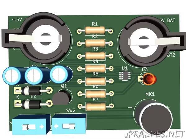
Voice level meter
Utilizing the NE5532 operational amplifier, a voice level meter circuit assesses audio signals. NE5532 amplifies input before rectification, and smoothing yields a DC voltage proportional to audio strength. This scaled voltage is shown via LEDs, offering prompt audio intensity feedback. This design harnesses NE5532’s audio volume monitoring and control capabilities across applications.
Voice level meter Pinout and functioning
Utilizing a peak-level hold circuit, LEDs retain brightness after voice input peaks, gradually fading. Wiring completed, switch turned ON. The earphone functions as a mic, activated by loud sound. LED brightness spikes and fades. The signal passes through the PNP transistor to the operational amplifier (+ input)—100F capacitor safeguards output. The capacitor discharges via a 47K ohm resistor, dimming LED. LED’s illuminating voltage flows to amplifier (—) input, compared to the earphone’s signal—capacitor charges when the signal’s larger, with no output for smaller signals. LED brightness is adjusted via a 47K ohm resistor or 100F capacitor. See the schematic for details.”