
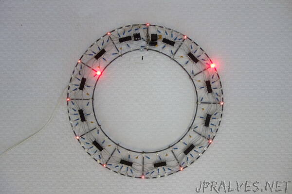
“One day I wondered if it would be possible to make a wall clock out of two concentric rings with leds and all electronics suspended between them. Well, now I know. For this clock there’s no need for a circuit board, in fact, it looks even cooler without. Especially with blinkenleds. This article is about my first circuit sculpture.
Design
After working on the wedding gift for Jeroen and Mingming, I thought a lot about making cool looking electronics. So I got this idea for a clock, drew a rough sketch, and then forgot about it.
Some years later I found that sketch again and decided to see if I could actually build it. This time I made a more detailled sketch and used a handful of parts to see which size would work best for the clock. The result is 240 mm (9.5 inch) diameter for the outer ring, and 160 mm (6.3 inch) for the inner ring. It won’t be a very big clock, but if the rings were any wider, the electronics would look very small in comparison.
Once again, form from function. You start with a circle of leds for the minutes and a smaller one for the hours, add metal rings for support, suspend the electronics in the space between the rings. That is all you need. I like that the centre of the clock remains clear, just like the sides of the bookcase for ring binders. Everything you need is contained within the ring itself. The clock looks a bit like a necklace.
Frame
The frame is made from 2 mm (0.08 inch) steel wire. The wire I had was all twisted up, so I cut two pieces and straightened them by twisting between the bench vise and a cordless drill. To make the ring shapes I bent the pieces of straightened wire around saucepans. It was difficult to make the ends meet for soldering, so I routed a jig to keep everything in place with some screws and washers, so I could solder in peace.
Soldering galvanised wire with solder meant for electronics didn’t work very well. It took a lot of time, heat and solder to make things stick at all and the result was a poor joint. Trying some s39 flux meant for soldering copper water pipes turned out to be a huge improvement. Now everything stuck perfectly at the slightest touch of a soldering iron, with only a fraction of the solder I had to use before.
The spokes between the rings were not in the original design, but without them there was nothing keeping both rings together. The spokes resemble hour indicators, which might make the clock more readable. First I tried to solder spokes between the rings but it turned out to be a lot easier to solder them on top of the rings instead. This also added a bit of depth to the sculpture.
If I were to build another frame, I would hard solder or weld the frame. This would be sturdier and won’t come apart later on when soldering electronics to the frame.
Electronics
The electronics are chosen for both functionality and looks, as they will be responsible for telling time as well as the look and feel of the sculpture. For this design I prefer the old-and-a-bit-crusty look over futuristic-and-clean. So no Neopixels, esp32 or SMD parts this time, but conventional, old-school, through-hole components. It should look like something made in the 1970s.
While the design process is described here in discrete steps, in reality many steps are intertwined. Most choices are made by roughly working out the implication of both versions and then choosing which design fits best.
Microcontroller, logic ICs or discrete DTL
The thought of building everything out of discrete diode-transistor-logic had crossed my mind, but that would be quite a bit more complicated than I wanted this project to be. Let’s use integrated circuits where possible.
Making a clock entirely from 7400-series logic ICs is absolutely possible. There are many clock out on the internet (and in peoples homes) that do exactly this. But at this point the requirements for this clock are not exactly clear yet, so some experimenting is in order. And every change would mean rewiring the logic, or even adding or removing ICs.
Using a microcontroller offers by far the most flexibility, but it does feels like cheating in a mock-1970s design. On the other hand, the possibilities are enormous. There could be an hour chime en it would even be possible to PWM the leds. And development cycles would be a lot quicker than any of the alternatives. Maybe having a microcontroller would not even be all that noticeable when it’s in a through-hole package, all in all it’s just another DIP on the wall.
Microcontroller
To stick with the low(ish)-tech theme, I went looking for a minimalistic microcontroller. Since I have worked with AVRs before an ATtiny seemed a logical choice. The smallest AVR that fitted the bill, both in terms of physical size and specification, is the ATtiny13a. It has 1k flash, 64 bytes ram, a 9.6 MHz internal oscillator and comes in DIP8.”