
“We built the car employing a variety of transmission methods. But what about a car that can be controlled over WIFI.
WIFI Control Car – Arduino Concept
“We built the car employing a variety of transmission methods. But what about a car that can be controlled over WIFI.”
WIFI is the most promising technology right now, and developers are always working to improve it. This technology is prevalent today and will be for many years to come. WIFI with low power consumption has also been developed. So let us concentrate on this technology today. We created a car that can be controlled via WIFI. If you host your IP address on a website, you can control it from anywhere in the globe, but we’ll stick to local WIFI for now. So, let’s get started.
About the Node MCU and the Car
Node MCU is an ESP-32S microcontroller (MCU) similar to the 328P, except it has WIFI incorporated into the ESP-32S. This is a fantastic resource for IOT newcomers. It can connect over WIFI and can function as a Hotspot. See the diagram above for the pinout. In the Arduino code, the GPIO numbers will be used.
Now, in this situation, the Node MCU connects with my router and generates a local IP address, which we can enter into our mobile device or computer (both of which are linked to the same router) to see a webpage appear with various buttons that allow us to operate the automobile. You can now control the car with the help of the website.
Connections and Uploading Code
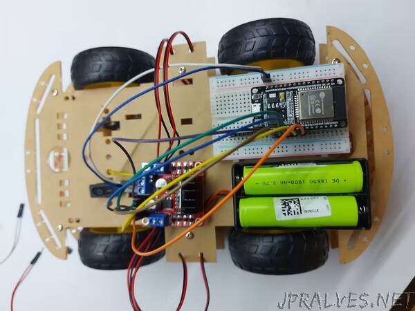
Set up your chassis. Connect motors and wheels and the caster wheel with screws. Solder wires with motors and connect them to the sockets of the driver.
See the figure above and connect. Connect your motors as per your configuration. If you are connecting your motor for the first time with the L298N driver then at first run a code for moving forward with the UNO. Then give it a try to the right and then the left. Backwards will follow it. It will be just a case of digitalWrite(). Comment freely if you are not okay. Power is required for the Node MCU as well as the L298N. It will be better by using a different supply for the two things. Give 5V from the power bank at the Vin and GND of Node MCU. You can use 9V or 12V for L298N. The whole process is rather easy. See the pictures given in the report and refer to the pinout pic of Node MCU. You will understand it better.
Opening Browser
Get into the website from your device browser. You can see the following webpage. It’s already been a host on a free domain site. Press any button and run the car, if not running, check the power supply given and for any loose connections happening. Do not give Node MCU beyond 5V. You can use 12V for the L298N. So now you can enjoy riding the WIFI-controlled car.
Hardware Required Table
- Node MCU WIFI ESP-32S
- Motor Driver L298N
- 4WD Smart Robot Car Kit
- 4 DC Motor
- 4 Wheel
- Breadboard 400-Tie
- 2 Battery 1800mah Battery
- Battery Box
- Jumper Wire 20cm 20 pcs
- Hot Glue Gun
- 2 Glue Sticks
- 1 Switch
Process of this WIFI Controlled Car
When this WIFI-controlled car is powered on, the Node MCU board connects to the WIFI connection. Then, when you press the Commands (Forward, Backward, Left, Right) buttons on the interface created with HTML coding and has live hosted the site, those values will be sent to the Node MCU board via the web cloud. Then, the gear motors rotate according to those values. The L298N motor driver board is used for this. Also, the speed of these motors can be controlled by the slider created on the website.
So, let’s make this smart car step by step. The required components are as follows: -
Used the necessary items and quantity with the help of the above hardware required table.
- Secondly, glue the four-gear motors to the car kit board, to do this, use the hot glue gun.
- Thirdly, attach the motor driver board to the top of the foam board. Afterwards, connect the gear motors to the Motor driver board. For that, use the below circuit diagram.
- OK, now glue the breadboard as follows. Then, attach the Node MCU board to the breadboard.
- Next, connect the motor driver board to the Node MCU board. For that, use the above circuit diagram.
- Now, connect the battery holder with the GND and 12v terminals on the motor drive board. After, glue it onto the car kit board.
- OK. let’s set up the website. After connecting your device to the WIFI and go to the link in the above “web & app interface made to send commands” page.
- Lastly, attach the batteries to the battery holder and turns ON your smart car. Now, go to the site: - http://wificar.c1.biz/ project and control it easily. OK, enjoy this project.
Learning Outcomes
When discussing the learning outcomes related to the group project they can be discussed in many different areas.
Since the main focus of this project was applications of the concept of computer architecture, this helped us a lot in getting proper insight into this module. We were presented with the opportunity to understand how to apply the theoretical knowledge we gained in lectures practically in real-world situations.
Though this is not subject-related, it should be mentioned how this group project helped us a lot in developing our skills in working as a team and also contributed to developing our research skills. This also allowed us to get to know our batch mates and interact with them.
We also got this wonderful chance to learn about the IoT and the robotics fields and how the concepts of computer architecture can be used in those files because of this project.
In addition to that learning, AutoCAD and Adobe Illustrator 2020 for the A3 poster (in doing graphics and illustrations) was an added advantage since most of us did not know much about graphics designing.
We also built the model over selves and did the coding part too.
Findings
When talking about the findings related to the topic, we selected for this group project we can categorize them under the following topics:
1. What are microcontrollers?
- We found a lot of things about:
- What micro controllers are,
- How they are used, for what they are used for.
- How they function and help with our daily activities.
2. How to make proper use of the motor driver used in our model.
3. How the proper usage of batteries affects the functioning of the model
4. All the codes used were written by us and we had to go to a trial-and-error method in programming the apparatus.”