
“The idea of using Arduino for measuring camera shutter timings is not new. What I’ve tried to do here, is to make a modular system with a set of features normally offered in professional testers, at the same time to keep its design simple and available to reproduce using off-the-shelf components.
Usually, time counting and/or light integration methods are used to test cameras. For the time counting method, you need a light sensor, a time counter, and a simple light source. With such setup you can measure exposure time(s) provided by a shutter, curtains travel speed of a focal plane shutter, flash sync contact delays, etc. For the second method, you’ll need a photosensor able to measure the amount of light and a calibrated light source. With such setup, you’ll be able to measure actual exposure produced by a system “camera+lens”, light meter accuracy, operation of auto-exposure cameras, etc.
This tester allows you to perform both time-based and light integration tests and calibrations of film cameras.
Main parts and components
Camera Tester uses Arduino Nano compatible board for processing. Arduino mounted on Shield PCB which connects all peripheral devices to it via three sockets. Each socket has a pin for automatic device identification. Device identification is based on a simple resistor divider, which is present in each sensor or light unit. Such approach allows to make the user interface much simpler.
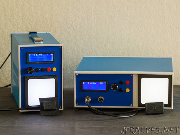
Controls are mounted on Keypad PCB, and include Rotary Encoder, and “Mode”, “Menu”, “Start” and “Stop” buttons. Dedicated “Start” and “Stop” buttons are used to avoid using interrupts and increase the accuracy of measurements. Thus, during the test, all other controls are disabled. Keypad itself was designed in two form factors (further named as “vertical” and “horizontal”) for the convenience of mounting Tester in various enclosures.
For time-based measurements, you don’t need a specialized light source, either a precise alignment, etc. The best choice of light source would be a standard desk lamp with an incandescent light bulb or bright LED panel placed in front of a camera in the proximity of 5-15cm. Recommended brightness is about 15EV, however, the Tester will work within a range of 13-16EV and readings may vary slightly. But, keep in mind, that photodiodes used for the Sensors are most sensitive to red to infrared light. Thus some bright white cheap LEDs (with color temp 6500K and poor CRI) won’t work, because their spectrum lies mostly in the blue range.”