
“The PID Temperature Control of a miniature thermal chamber is a system designed for teaching the fundamentals of Process Control.
Story
The PID Temperature Control of a miniature thermal chamber is a system designed for educational purposes. It can be used as an inexpensive lab for developing an understanding of process control and the effects of process dynamics on selecting the optimum PID (proportional, integral, and derivative) tuning constants. The system can be implemented inexpensively and would be ideal for a student doing an on-line course in process control systems. The system allows operating, PI, or PID control with reverse or forward (direct) acting control., by using selectable final control elements (resistive heater, or variable fan speed). The system provides 2 sets of process dynamics by tightly coupling a temperature sensor to the resistive heater or alternatively using a sensor in the centre of the chamber. These very different process dynamics require very different sets of PID tuning.
The system hardware consists of the miniature (100x68x50mm) thermal chamber, a control board and an interface board.
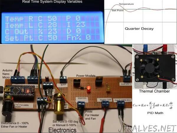
The control board consists of an Arduino Nano, a setpoint potentiometer for setting desire temperature in deg C and a disturbance potentiometer, selectable for either heater or fan. The outputs from the Nano are 2 pulse width modulated signals that produce a variable DC voltage that drives the fan and heater.
The interface board utilizes 2 N Channel power Mosfets and uses the PWM signals from the Nano to produce a PWM output with a maximum voltage of 12VDC to supply the thermal chamber heaters and fan.
The thermal chamber consists or 2 Cement resistor heaters of 5 watts each, a 12VDC fan, and 2 LM35DZ temperature sensors. One of the sensors measures the air temperature of the Chamber, while the other sensor is firmly attached to one of the temperature resistor heaters.
The following image shows a block diagram for the system. Note that the Arduino Serial Plotter is used to display the Temperatures and Setpoints. The following are the commands that are set from the Arduino IDE Serial Plotter:
LM35_1 - Sets the PID controlled variable as the temperature of one of the cement resistor heaters. In the phot, it is the cement resistor on the right. Tuning Constants are optimal using Ziegler Nichols Open Loop method.
LM35_2 - Sets the PID Controlled variable as the temperature of the sensor in the middle of the chamber. Tuning Constants are optimal using Ziegler Nichols Open Loop method.
LM35_1Fast - Sets PID controlled variable to heater temperature sensor, PID tuning constants for a fast oscillatory response
LM35_1Slow - Sets PID controlled variable to heater temperature sensor, PID tuning constants for a slow stable response
LM35_2Fast - Sets PID controlled variable to air temperature sensor, PID tuning constants for a fast oscillatory response
LM35_2Slow - Sets PID controlled variable to air temperature sensor, PID tuning constants for a slow stable response
Reverse sets the PID controller to Reverse acting, where the temperature is controlled by the PID adjusting the voltage to the cement resistor heater. The fan then can be manually adjusted by the potentiometer to act as a disturbance.
Forward sets the PID controller to Forward(Direct) acting where the temperature is controlled by adjusting the fan voltage, and therefor air flow to the chamber. The heater then can be manually adjusted by the potentiometer to act as a disturbance.
Manual disables the PID controller and allows the the setpoint potentiometer to fix either the heater or fan setting from 0 to 100%. There is no feed back. This is referred to as open loop.
Auto enables the PID controller, either Reverse or Forward acting.”