
“In this project, we have designed a touch sensor that powers LED when the test point terminals are touched with a finger.
Have you wondered about how to come up with a Touch switch by yourself? Yes! with the invention of transistors, everything became possible. In this project, we are going to build a simple Touch sensor circuit by using the BC547 transistors and other supporting components. This type of switch can be used in modern portable torches and lighters whereby touching the torch, the lamb is powered on, and on releasing it the torch goes off. This is a vital system that can help in energy saving. Mechanical switches are a risk to energy since if you forget to switch your torch off, you will lose your battery power unnecessarily.
Let us first understand the BC547 which is our main component in this system.
Brief Intro. about BC547
BC547 is an NPN bi-polar transistor that has three pin-out, the collector, the base, and the emitter. The transistor has a gain of between 110 and 800 and this is the value that determines the amplification of this transistor. The collector has a maximum current flow of 100mA hence loads consuming more than this current cannot be connected to this transistor. Biasing this transistor requires us to power the base with 5mA of current. Biasing the transistor allows the flow of at most 100mA of the current across the emitter and collector. The transistor can operate in both saturation and cut-off regions.
The transistor has two applications where it can be used as a switch and as an amplifier.
In our project, we shall be using it as a switch.
BC547 as a Switch
When used as a switch, it operates in saturation and cut-off regions. We shall use the transistor to drive our LED module.
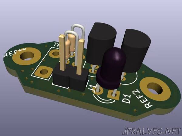
Requirement:
- BC547 Transistors 2
- Resistor 470R 1
- Resistor 10K 1
- LED 1
- JST connector 01x02 1
- Test Point 1
Circuit Description:
Note that the circuit was designed using the KiCAD EDA.
The two transistors are interconnected to act as a Darlington pair. Transistor Q1 is amplifying the gain first then it is further amplified and multiplied by the transistor Q2 for us to end up with a high gain. The high gain is very important as it makes the circuit very sensitive to small currents passing through our skin hence powering on the LED. The circuit can be operated by either 6V, 9V, or even 12V. For 6V use a 330R resistor, for 9V you have to use a 390R resistor and for 12V you will use a 470R resistor. In place of the resistor R1, you can employ the use of a variable resistor of about 200K so that you can keep adjusting the sensitivity of the circuit.
When you touch the test point TP1, a small amount of current flows through our skin to complete the circuit hence firing on the LED.”