
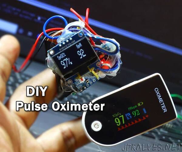
“Hello all, I Hope you all are safe. I’m here with another project which you can build with very few components. In this writeup, I’m going to tell you, how you can make a Pulse Oximeter by using Arduino and some very basic electronic components, in this pandemic situation of Covid19 most of us probably familiar with oximeter which we use to measure oxygen saturation in blood and the pulse rate. So let’s see..
How An Oximeter works?
Basically Oximeter calculates the percentage oxygen saturation in the blood on basis of amount of different light absorb in it. Oximeter has One photodiode and two LEDs one is Red LED & another one is InfraRed LED, both LEDs are switched one by one on a certain frequency. To take measurements fingertip is placed in between of photodiode and LEDs as shown in the picture. Oxygenated blood absorbs more Infrared Light and passthrough the more red light and Deoxygenated blood absorb more red light and passthrough the more InfraRed Light. Processor calculates the ratio of red light received at photodiode and Infrared light at the different time interval. for more details on Pulse Oximetry Basic Principles and Interpretation visit this or see this pdf on Pulse Oximeter Fundamentals and Design from NXP
Components Used:
Arduino Pro Mini X1
OLED Display X1
Transistor BC547 X2
Photo Diode X1
IR LED X1
Red LED X1
Resistors
10K x1 , 4.7K x2
9V Battery X1
Battery Cap X1
LM7805 X1
Clutcher X1
Just collect all the above Components.
let’s see the Circuit Diagram.
The oximeters can also build By using Max30100 Sensor which is specially design for measuring pulse and oxygen saturation in blood. It’s not that critical to make an pulse oximeter using it, since It combines two LEDs, a photodetector, optimized optics, low-noise analog signal processing to detect pulse oximetry and heart-rate signals. and I2C interface. But I thought to make one oximeter with it’s basic components used in Max30100 sensor i.e. 2 LEDs and Photodetector. I took a general purpose Photo Diode and grind it using grinder to make it flat and thin so that it can receives max light from the source, originally it is in round shape and dark color, these two factors block the more visible light and this is not good for our project, since we are using red visible light as well as the invisible infra red light. Similarly I grinded a red LED and a Infrared LED from one side, and combined them using super glue. Took a hair clutcher and put Photo Diode at one side of it and combined LEDs at another side of it as shown in the picture. After this I connected all the components as shown in the circuit diagram. I didn’t used PCB here since there are very few components, so I solder them just around the Arduino board and fix them using hot glue. to power this oximeter I using the 9Volt battery.”