
“Hello all.
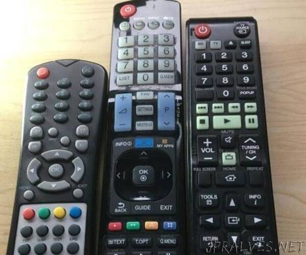
A disclaimer right up front, I didn’t shrink the remotes and that’s not a photo of my remotes through a microscope. But what I did do was shrink them down to the buttons I use the most. Not even sure what most of the others do!
However, most of you will know what this image represents. A collection of remotes that miraculously develop flat batteries all at the same time, become chew-things for pets and small children, or get swallowed by the couch and remain hidden until you have basically disassembled it.
Add to that, trying to explain to house/pet/child sitters how to switch to [un-named] casting device/BluRay/normal TV and which volume control affects which output. Invariably you get home and they’re reading a book.
I’ve been thinking about this one for a while and finally built it, encouraged by the latest contest “Remote Control”.
Let’s begin();
This project requires the building of 2 circuits, one can exist in breadboard form since it’s only there to read your remote codes.
Receiver (Left):
Any arduino will do, for this instruction I’m using a Pro Micro,
An Infrared receiver (Rx) diode. You can buy these in Rx + transmitter pairs.
Transmitter (Right):
Any wifi ESPxx module will do, I’m using a Wemos D1 Mini,
IR Transmitter (Tx) - Can use more than 1 in parallel to increase reliability
A 1/4W resistor to limit the current to the LED(s), I used a 47ohm with dual leds.
At some stage you will need an enclosure for the Tx unit, near a wall socket so you can keep it powered on and line-of-sight to the target devices. An existing lamp stand works well. I used an old 50mm diameter LED ceiling light housing (nice anodised aluminium finish on the outside) and put a pair of the IR LEDs in parallel where the LED board use to be. Where and how you mount it will depend entirely on your room layout and availability of a 5v power source.”