
“I’ve recently been getting into chiptunes, including both writing music as well as programs to generate the sounds that play the music. My interest in sound generation goes back to 2018, when I wrote a small library for TI-84 calculators to control playback of 16 channels across four wave types on a connected Arduino, and later Raspberry Pi. The system was initially very primitive - it could only use sine, triangle, square, and sawtooth waves, and was only able to control the volume and frequency of the output. It also relied on PWM output through an RC filter, which sounded pretty crappy (but worked). Later versions added support for 8-bit PCM audio at 8000 Hz, but due to the space constraints of the TI-84, I could only store a few seconds of audio, even at such a crappy quality.
About two years later, I decided to expand on this a little bit. At the time, I was working on improving the plugin API for my fantasy terminal, CraftOS-PC, and I wanted some stuff to demonstrate how it works. I also had ported a Game Boy emulator, but the sound support was abysmal, relying on writing WAV files to disk and then playing them back, hoping it wouldn’t sound too terrible. The result was what I call craftos2-sound, or simply the sound plugin. It supported an extensible number of channels (4 by default, but I usually use it with 16), which can each have any wave type, unlike the TI-84 sound project, which only had a non-configurable four channels per wave type. It also had volume and frequency control, as well as stereo panning, automatic fade in and out control, and a new noise wave type. About a year later, I released version two of the plugin, which added a new custom wave type with up to 512 user-supplied samples (plus interpolation modes), pitched noise and reverse sawtooth wave types, and a duty cycle option for square waves. The plugin used software generation of the waves, filling a buffer in real-time to be played by the operating system’s sound infrastructure.
My primary usage of the sound plugin was through my XM module tracker, tracc. While playing my modules using the sound plugin sounded better than playing back recorded samples of the waves, I felt like I was cheating. I was playing chiptunes - songs meant to be played through 8-bit analog sound generators - through a software reimplementation that output PCM data, and was then mixed and processed along with the rest of my system’s audio output. It felt too clean - I wanted to have a real analog synthesizer that I could plug into my computer, which makes sounds from the tools I already had.
Sound generation: an overview
Before we dive into the implementation details, I’ll give an overview of the history of sound generation. Most sound today is what is called streamed or sampled audio: the files store a sequence of samples that directly represent the voltage sent to the speaker over time, which correlates to how far out the speaker cone is. The files are mixed and played back directly, with the only programmable generation coming from the original sound and music design, or a synthesizer instrument that was sampled and mixed into music. This is similar to how binary programs are compiled into basic instructions before being distributed.
However, one drawback of streamed audio is that it takes a lot of data to store the audio. For CD-quality audio, you need 44,100 samples every single second per speaker, and CDs use 16-bit (two byte) samples and two speakers (stereo), which adds up to 176 kilobytes per second. This is why a CD can only store just over an hour of music in three quarters of a gigabyte. Thankfully, some very smart people have come up with algorithms that can throw away a lot of useless or hard to hear parts of the audio, which can bring a full CD down to about 100 megabytes. But these algorithms take a lot of computing power, which is not good when you need to play sound on a system with a slow CPU and not much data space.
To avoid the size or computation requirements of streamed audio, early computer systems chose to use generated sound instead. The most primitive systems, like the Atari 2600 and IBM PC, chose to only include a single basic 1-bit beeper, which can only send out a full on or full off signal, as opposed to the various in-between values used in most audio. This creates a square wave, which is the basis of the 8-bit era of music. However, because there were only two possible states on the output, beepers were not useful for much beyond simple sound effects, and possibly very simple music. In addition, the CPU was in charge of all of the sound generation, which took away time from actual gameplay.
To allow for more advanced music, later systems chose to use a dedicated chip or circuit to handle making music asynchronously from the main processor. These chips often used more analog circuitry to allow for those in-between values that digital processors can’t produce by themselves. The chips exposed an interface for programming the generation parameters that was designed to connect to the main CPU easily. In fact, some circuits were even embedded into the same package as the CPU.
The NES’s Ricoh 2A03 microprocessor included a programmable sound generator on the same chip as the main 6502 core. This PSG included two square wave generators with configurable frequency, volume, and duty cycle parameters, a triangle wave generator with configurable frequency (which was a good substitute for smooth sine waves), a noise generator with 16 presets, and even a DPCM playback channel, which can play very rudimentary 1-bit sampled audio.
The Commodore 64’s SID chip was much more advanced, and included three channels with square, triangle, noise, or sawtooth waves (configurable), plus a number of filters on top of the waves generated: attack/decay/sustain/release filters, ring modulators, oscillator synchronization, and a single low-, high-, or band-pass filter. These could be combined to make complex music, which was a defining feature of many popular Commodore 64 games.
One advantage of programmable sound generators was that no extra data was required to play sound. In fact, the music could be directly coded into the application, meaning the amount of data required could be condensed extremely small to fit into the few kilobytes of space available on early ROM chips.
Eventually, as storage space increased and analog circuitry became more advanced and cost-effective, computers started using chips with wavetable synthesis, which played back pre-set or configurable PCM samples using similar parameters to PSG chips. Then FM synthesis chips took over the sound scene, with Yamaha leading the movement - their OPL2 and OPL3 chips were used in a large number of PC sound cards throughout the ‘90s. Finally, around the time CDs became mainstream, streaming PCM sound cards replaced all other sound chips, allowing true audio reproduction without any generation circuitry.
First attempt: Raspberry Pi Pico
In a past project, I experimented with audio playback using my Raspberry Pi Pico. I managed to play back 22kHz 8-bit WAV audio with okay quality using the PWM pins on the Pi. Because of this, I figured it might be possible to instead generate my own audio from wave synthesis instead of disk playback.
My first step was ripping the sound plugin in two: the sound generator would go on the Pico, and the Lua interface code would stay in the plugin. Then I had to rewrite the generator to output in real-time instead of writing to a buffer. Finally, I had to write a small serial layer to connect the two over USB. Luckily, the generation code was built somewhat modularly, so making it streamable wasn’t too hard. Instead of using a fixed clock as the PCM output had (48000 samples per second), I updated the position of each channel’s period using the system clock measured in microseconds, and I added the difference between the last update time and now for every loop. This allowed a variable sample rate, which came in handy later on.
Now PWM output is pretty complicated on the Pico - you have to set up these clock dividers and limits, so it’s not just a straightforward “send out a wave with this duty cycle”. This makes the PWM hardware of the Pico quite versatile, and I even considered the possibility of using these functions to generate pure square waves. However, I just needed to be able to send out a specific duty level as fast as possible, so I initially set the clock divisor to a really low value, which makes it run super fast. Unfortunately, this did not turn out well - it caused a lot of crackling and general ear salad - so I put it back to 1.0, dropped the bit depth from 16 to 8, and called it a day.
Once I was able to get the generator working on its own, I plugged in the sound plugin and started testing. The first thing I noticed was that the data rate was very slow. Even after setting the serial baud rate to 115kbps, I was getting the same abysmal speeds. It wasn’t until I took a look at the USB communications in Wireshark that I discovered the true culprit. Every single byte I sent was being sent as its own packet, adding about 64 bytes of header to the single byte message. This effectively brought my speeds down to 220 bytes per second, or about 9 messages per second for 8 channels. The reason this happened was because I had disabled buffering on the file, which I had hoped would reduce the chances of commands getting stuck in the buffer. I fixed this issue by re-adding a small buffer, but making sure to flush it every tenth of a second to avoid any messages getting stuck.
My next issue was that the output sounded super terrible. It sounded like it had a low sample rate, which I discovered was the case after plugging the audio into Audacity and viewing the waveform it was generating. The wave was very aliased, with multiple samples set to the same value before jumping up to the next level. At first, I thought it was a PWM issue, so I tried fiddling with the clock speeds, but this only made the sound worse. Eventually, I tried reducing the channel count, only to find that the sample rate was back to normal. The code was too slow to run more channels! This was a pretty unfortunate discovery, as I like music with lots of channels, and 4 is definitely not enough for most of my stuff. I was able to partially remedy this by making it so it only processes channels that are active, so it will have a good sample rate with few channels, but too many channels will drop the sample rate once again. This was only possible because I decided to use a flexible clock system in the wave generation function.
Eventually, I made the choice to stop working on it, as the CPU was just not powerful enough to run that many channels, despite having a 133 MHz processor, which is way faster than most microcontrollers on the market. I could have optimized the code, but I really didn’t feel like putting more time into it either, so I moved on to find a better solution to what I was looking for.
Designing my own system
My main requirements for a sound card are at least 8 channels (16 ideally), which can be composed with multiple chips; square, triangle, sawtooth, and noise waves; frequency control from 20 to at least 8000 Hz; and at least 6 bits of volume control on all channels. At first, I tried looking for some chips that I could combine to make a board I wanted, starting from Wikipedia’s list of sound generation chips. Unfortunately, after scanning the list, none of them were able to fit my requirements, and most of them were out of production too. It was obvious that trying to use pre-built chips was a dead end, so I had to make my own circuitry.
Next, I took a look at using analog circuits to generate the waves. This would give me the most accurate sound generation. However, I’d need to make one circuit per channel for each wave type, which is a lot of circuits to wire up, and required a large number of components that I didn’t have. This route was also a dead end, so I threw away that idea too.
As a compromise, I figured I could use digital circuits to generate the waves for each channel, then combine them all into one signal using an analog op-amp. This would allow me to use just one chip per channel, meaning no redundant/inactive circuits when using different wave types. I could also program the behavior of the generator through code, which I’m much better at than electronic circuitry. All of the chips would be controlled by a main controller, which receives commands over USB and delegates them to the chip the command is meant for. This plan would be my final decision.
First, I needed to find a processor that could support the inputs and outputs I needed. The primary requirement was a built-in DAC with at least 8-bit resolution. I also needed a suitable speed for audio output, so at least 48000 sample periods for second, or assuming 50 instructions per sample and one instruction per clock, about 2.5 MHz. Finally, I needed enough pins to be able to communicate data with the main controller - an external interrupt pin would trigger a data connection, a clock pin would tell the chip the bus is ready, and one or more data pins would hold the data. A parallel data bus would help reduce the time transferring data, which is important in a time-critical application like audio playback. A cheap chip would be great, too, as I didn’t want to spend too much on this project.
After some searching, I decided to settle on the PIC16LF1613 microcontroller. This chip has an 8-bit DAC, 12 I/O pins, a 32 MHz clock (with 4 clocks per instruction = 8 MIPS), 2048 instructions of program memory, and 256 bytes of RAM. This was a great choice for the application, so I picked it for the generator chips. Once the chip was chosen, I started work on a prototype schematic in Fritzing.
To save on wiring and pin allocation, I chose to share the data and clock pins across all generator chips. To select the chip to send the command to, I decided to use a shift register to be able to use an extensible number of channels with just three pins. The shift register’s outputs go to the interrupt pins, and the selected chip is sent the interrupt only after pulsing the output enable pin on the register.
I used the LM358 op-amp to mix the channels together. It’s configured to add all of the channels together, with a potentiometer to adjust the volume.
Programming the generation chips
While I waited for the parts to come in the mail, I wrote the code for the generators. PIC microcontrollers use the MPLAB X IDE for programming, with the XC8 compiler. Luckily, the IDE runs on Linux, so I had no problems installing and running it. I made a new project, configured it for the 16LF1613, and it started me out with some basic code for the chip.
Even though the chip and IDE were made to run C code, I wanted to write the code in assembly so I could use the chip clock as a stable clock for generating waves, instead of trying to rely on the limited-resolution timer. This required writing the main generator loop in a way that every single path took the same amount of time (I’ll describe this later). Unfortunately, MPLAB X does not have great support for writing pure assembly programs. When compiling some basic main code, it kept complaining about missing or duplicate symbols and entry points. Eventually, I found that I could disable linking the C startup code, and after adding a few dummy sections that the linker expected, I was able to get pure assembly running in the IDE.
The program consists of two primary sections: the main run loop, and the interrupt handler, which reads commands from the parallel data bus and stores them in memory. I started by setting up the memory layout that I would use. The main configuration section of memory uses 7 bytes, which holds the wave type, volume scalar, square wave duty cycle, a 16-bit value for the current position of the wave, and a 16-bit value holding the increment per loop, which is calculated from the frequency selection. The 16-bit values technically function as a fixed-point number, as the generators only use the high byte - the low byte is just for accumulating the in-between steps while looping.
The interrupt code is mostly simple: it waits for the clock signal to be raised high, then checks the high two bits that were sent (which corresponds to the two data bits on the A port). It then uses a series of jumps to select the command to execute. For wave type, it takes the low 3 bits and stores it in the wave type register. If the wave type sent is square, it then waits for an additional byte, and then writes that to the duty cycle register. For volume, it waits for the next byte, then writes all 8 bits to the volume register. For reset, it simply executes a reset instruction. However, for frequency, I had to use some special code to convert the frequency into an increment value.
I spent some time working through an equation for converting the frequency to an increment that would make computation much easier in the main loop. Eventually, I managed to bring it down to a single multiplication between a constant and the frequency. One problem - the PIC architecture does not have any built-in multiplication instructions. To resolve this, I found some code for multiplication online that I implemented into my program. The scalars I needed to multiply by often ended up being smaller than 0, and I needed to multiply the 16-bit frequency, so I used a 24x24-bit multiplication algorithm with the low byte being a fractional portion. The low two bytes are then discarded (as they represent the fractional results - mind that multiplying one decimal place by one decimal place results in two decimals in the product), and the middle two bytes are stored in the increment registers (the top two are discarded).
After writing the interrupt code, I started the main code. First, I had to initialize the memory and peripherals - this consists of writing a bunch of constants to various parts of memory. After that, I started writing the shared code that would be used for all wave types. This consists of a test to skip generation if the volume or frequency is 0, a jump table to go to the code for the specific wave type, a scaler to apply the volume level to the output of the generators, and some addition to add the increment value to the position register + looping back to the beginning. Since these parts are shared by all wave types, I didn’t need to worry too much about counting clock cycles - I just needed to make sure it didn’t run too long (I had a 166 cycle budget to reach a 48kHz minimum sample rate).
Writing the actual wave types was surprisingly easy. The square wave only requires comparing the position register with the duty register, and setting the output to the volume register if less than, or to 0 if greater than. The sawtooth wave simply copies the position register to the scaler input; the reverse sawtooth subtracts the position from 65535 (the maximum value). The triangle wave is a combination of both sawtooths: if less than halfway, use a sawtooth; otherwise, use a reverse sawtooth. Then double the output and put it into the scaler input. Sine waves use a lookup table in program memory, and noise waves use a very basic random number generator.
To make sure all of these wave types use the same number of clock cycles, I counted the cycles in the longest part, then inserted no-op instructions in all of the others to match the longest one. Since the square wave skips the scaler step, I used a loop to wait for the same amount of time as the scaler. But for no wave type, I did not need to keep track of the cycle count, as this part never updates the counter so it doesn’t need to keep a constant clock rate.
Before deploying onto a device, I used the IDE’s simulator to test that the interrupt code and the basic generation loop worked. After fixing a few bugs, it was ready to be tested on real hardware. But to be able to actually interface with it, I had to write the Pi Pico code that interfaces between USB and the microcontroller data bus. I was able to copy the command parsing code from the old Pi Pico project, and added in a few functions to select and interrupt the requested channel’s chip, as well as to write data to the bus. This ended up working out pretty well when testing.
Assembly and wiring
Before assembling the entire 8-channel board, I tested a single channel first. I first placed down one programmed MCU on a solderless breadboard, and added the proper wires to the Pico. Since I was testing a single chip first, I just had the Pico directly interrupt the chip: no shift register yet. Then I sent the initial code to the Pico, and started up CraftOS-PC with the same sound plugin I used for the old Pico code. I initially had issues with all of the channels’ commands being thrown together, but adding a channel filter fixed that issue. All of the waves turned out surprisingly good (except for noise, which had too quick of a period for good noise), and the triangle wave even has curved lines like the NES’s triangle wave did, which adds a distinct sound profile from a normal straight triangle wave.
Next I added in the shift register. I had some difficulty at first when trying to make sure it worked like I thought it did: it seemed to be pushing data in erratically, with random data going in, and the entire register being cycled in less than 8 clocks. I eventually realized that this was because I did not have pull-up/down resistors active on the input pins, so random data was being sent to the register. After connecting it directly to the Pico (and making the code work properly), it almost worked like normal.
I was noticing that the channels were now starting to mix with each other. But this shouldn’t have been happening as it was only sending an interrupt to a single chip at a time. After a lot of debugging, I noticed that the debug LEDs for testing were pulsing for all channels even when not selected. This led me to find that the MCU had a built-in pull-up resistor on the interrupt input, and that that pull-up was outputting voltage in the wrong direction back into the shift register, and that the shift register acts oddly when voltage passes back through its outputs. I was able to fix this issue by disabling the pull-up resistors, though I did have to add my own pull-down resistors since the shift register completely disconnects the outputs when output enable is off.
Eventually, I had it working like a charm. Finally, I added in the op amp to see if that worked the way I thought it did. I wired it up just like in the schematic, and mixed it together with my phone’s audio output for testing. The sound ended up being awful, but I realized this was because the phone’s output was louder, and it also had both positive and negative portions (while the PSG only generated positive signals). It appeared to work under the weird conditions I gave it, so I marked the prototype as ready to build.
I then moved on to building the full board. I ordered eight chips to start with, meaning eight channels of audio. However, I wanted to leave the ability to add more channels later, so when mapping out the board I left space for more channels - my goal was 16, but I managed to squeeze enough chips for 20 channels onto the board. (I had to put the potentiometer on a separate board to fit, but it still worked fine.) The neat thing about the architecture I designed is that adding on more channels is real simple - just add a few microcontrollers, add enough shift registers to cover all chips (8 MCUs per register, and they are easily chained together), and connect all wires but the interrupt to their respective bus wire. Then I soldered the sockets in, and popped the chips into the sockets.
Finally, it was time to wire them all up. Once I started figuring out how to wire it, I ran into a pretty big issue. I was expecting to be able to daisy-chain the data wires by twisting them together and sticking them into the same hole. However, in practice this did not end up working out at all. Because I did not want to have to desolder the entire board and rearrange everything to have 4-wide gaps instead of 2, I tried to find some ways to work around this.
For the power lines, which used thicker-gauge wires, I made a “bus wire” that I then soldered smaller connecting wires to periodically. But setting those up was tedious, so for the data wires I instead just tied groups of 4 wires together and soldered them to one single input wire, which was much quicker to put together.
After 12 hours of soldering, and a bout of nausea likely caused by improper safety procedures, I managed to only get 4 out of the 8 channels wired up. Since it took so long to do just the first four chips, I decided to save the other four for another day, and just rolled with the 4 channels I finished.
Testing the final product
With all of the wires connected (for the first four channels at least), I plugged it into the Pi Pico and turned it on for the first time. Before testing, I reprogrammed the chips to give me four different tones to make sure all chips and the mixer were functioning properly. But when I plugged it in, I got no sound output. I freaked out, thinking I blew up the processors (as I measured a weak connection between V+ and ground, but this was just from the chips’ impedances), but it turned out that the potentiometer I chose had a mute portion that cut off the sound completely.
The initial wave generation worked well, but once I started interfacing with the Pico to control the channels, I found that the configuration was spotty at first, and eventually it stopped working completely. Triggering a command without the data wires connected did not even trigger an interrupt, so I figured it must have been an issue with the shift register. I took the shift register out and connected it to the Pico on a breadboard with LEDs for debugging. I had to fiddle with the code a lot to get it working, but once it was I dropped it back into the board.
Unfortunately, I was still having issues with the shift register. I checked over the connections to the board again, and discovered that the wire I used to connect the clock signal was no longer working. After replacing the wire, configuration was working, and I was able to test it out using the plugin I wrote.
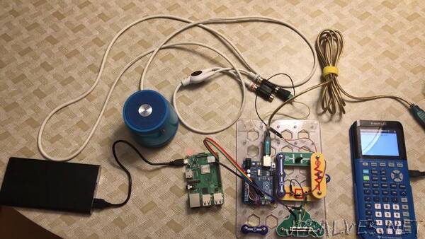
I booted up CraftOS-PC with the sound plugin for the Pico, and ran tracc with my Super Mario Bros. module. The theme immediately started playing, and it sounded great. The sound was a bit jittery, but I attributed this to the slow transfer rate of the Pico’s serial connection, which can be fixed with a custom USB protocol. The noise algorithm also sounded pretty bad (which I knew about), so I swapped it out with the exact same algorithm that the NES’s sound chip uses, using the same shift register method (except in software instead). Finally, there were also some slight pitch slurring issues, but this was caused by the interrupts taking away clock cycles from the precise wave generator, which resulted in parts of the wave being held for a few samples longer than it was supposed to.
I then tried it with other modules, and it worked even better. Here’s a recording of the module I think came out the best.
Final thoughts
I think this project turned out pretty well. I’m a bit disappointed it took so long to wire only half the board, and there’s certainly some improvements I can make beyond more channels (starting with adjusting the op amp to output properly balanced audio - currently it’s positive only, which isn’t great for speakers), but for what it is I’m happy with how it turned out. This was my first serious endeavor into assembly programming (besides some templated OS code and some playing with my own architecture), and having to work around the timing constraints of the generator code was fun.
Soldering for over 16 hours combined was Not Fun, but I did get a bit more experience in cleaning my iron, which has gotten very rusty over years of use. (This is something I’m not too proud of, but being able to instantly melt solder after properly cleaning was a real help.) I also got some experience with removing solder that I messed up, and I likely now have a lifetime’s worth of lead in my body.
I hope to expand this a bit in the future by designing a proper PCB. This would make the board much more organized, and reduces the amount of soldering I need to do. I’ve come up with projects that involve PCBs, but I’ve never pulled the trigger on actually ordering one, so fully designing and ordering one would be a great experience.
In any case, I like how it’s turned out so far, and I’ll probably be improving it some more soon. If there’s any significant updates, I’ll post an update with the new changes I make.”