
“This project exposes a 16 KiB window of a Raspberry Pi Pico’s RAM to a Commodore 64 via the expansion port. It includes a hardware design and software for the Pico C++ SDK.
The Hardware
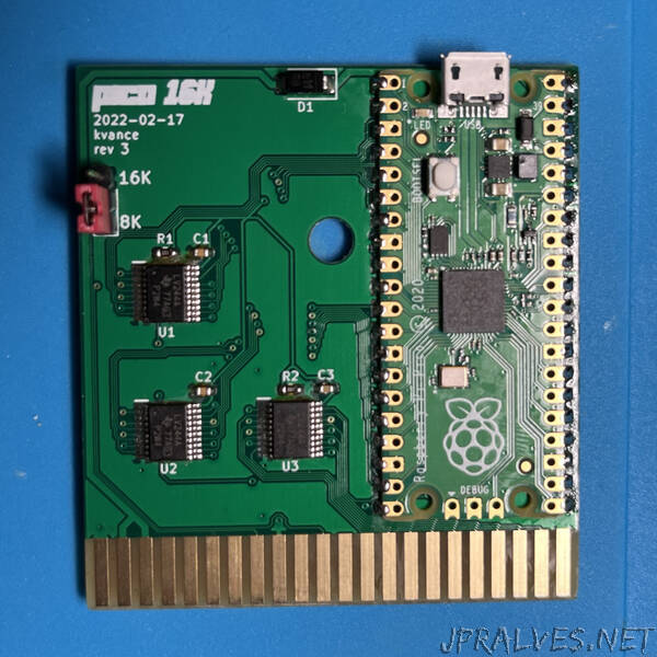
Schematic, PCB, and project files are in KiCad 6 format.
5V power from the expansion port is used to power the Pico. As suggested in the Pico datasheet, a Schottky diode allows the Pico to be connected to powered USB at the same time.
8-bit buffers bring the 5V logic levels on the address and data bus down to 3.3V to protect the Pico’s GPIO pins. This means that when the C64 reads from the Pico, it’s putting a 3.3V signal on the data bus. At TTL logic levels, this should be fine.
A switch allows you to toggle between an 8K ROM and a 16K ROM by pulling the /GAME line low. This loses half the address space, but lets you boot into BASIC.
The tolerances on the PCB design are compatible with JLCPCB. I ordered my prototypes from them with ENIG surface finish and gold fingers on a 1.6mm thick board. You can get them made much cheaper with HASL, but it will eventually scrape off as you reinsert the board.
The firmware
Given a 16 KiB-aligned base address on the Pico’s address space, four PIO state machines and two DMA channels handle reading addresses from the C64 address bus and writing the requested data to the C64 data bus. The CPU is not needed once this is configured.
To allow the C64 to communicate with the Pico, a 256 byte command area is reserved that will put that byte onto the RX FIFO for the CPU to consume. The CPU can put any value onto the TX FIFO to signal that it is ready for more commands.
Between the GPIO pins and the RAM, there are five logical components:
- address_decoder PIO state machine: monitors the /ROML and /ROMH lines for reads, checks if the address is for the special command area, and wakes up either the read or command state machines as needed. Two copies of this state machine run at the same time, monitoring /ROML and /ROMH.
- read PIO state machine: reads the address lines, sends the address to DMA, and writes the returned data to the data bus
- command PIO state machine: reads the low 8 bits of the address, and copies it to the RX FIFO for the CPU to handle. It writes the STATUS register back to the data bus, indicating if the CPU is busy or not. The CPU can indicate its readiness by writing any value to the TX FIFO.
- The special value 00 will not be sent to the CPU at all, allowing the C64 to poll the status register until the Pico is finished processing a command.
- DMA channel 1: write the incoming address to the configuration of DMA channel 2, triggering a read
- DMA channel 2: copy a byte at the requested RAM address to the read PIO state machine”