
“An attempt to build a beer pong playing robot with questionable results.
How to Almost Build a Beer Pong Playing Robot
In April of 2021 I was looking for a project to spend my ample amount of free time on. For some reason a beer pong playing robot popped into my head. At a high level I envisioned a robot that would use a camera to find cups and fire a ping pong ball at said cups. I decided a Raspberry Pi would be used as the “brain” and would handle the image processing. The Raspberry Pi would tell an Arduino how to orientate the firing mechanism. Having a 3D printer I planned to print a majority of the firing mechanism. Over the next year I would spend my time designing, testing, and redesigning various aspects of the robot in hopes of improving its accuracy. I am writing this to document all of the effort I put into to the project and in hopes of it helping someone else.
Prototype 1
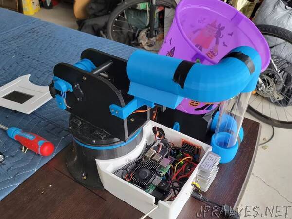
I start the first version of my robot by trying to come with a firing mechanism for the ping pong ball. The first thing that came to mind was emulating the throwing action of a human arm with a robotic arm. But some preliminary testing with an already built robotic arm and the power from hobby servos wouldn’t provide the torque necessary to throw the ball very far. I then had the idea of propelling the ball using a fan. I decided to use a spare blower fan from a Christmas inflatable. I started the mechanical with deciding on a rotating base for the robot. I already had the base for the Thor robotic arm (http://thor.angel-lm.com/) and decided it would suite the job. I then went on to design the adapter plate for the base mounting bracket for the launcher, and the launcher itself. In my first prototype the launcher was entirely 3D printed, comprising of a barrel and a hopper. The barrel had a servo with a rack and pinion used to stop the ball and the fan mounted at the end. The hopper also had a servo with a rack and pinion to load the ping pong balls into the barrel. The STL files for my first prototype of version 1 can be found in the following directory Prototype_1/STL_Files. Having the rough prototype of the hardware it was time to focus on the electronics. As stated before the “brains” of the robot would is a Raspberry Pi3 Model B which controls an Arduino Nano used for interfacing with other devices. The base is controlled using a stepper motor driven by an A4988 with a10k potentiometer to track the base’s position, the fans speed is controlled by a PWM driven MOSFET, and the servos are controlled via PWM from the Arduino. The electronics are power by a 12V ac adapter which is stepped down by a dc to dc converter for everything but the fan and stepper motor. I have created a rough schematic for the electronics in the directory Prototype_1/Schematics.”