
“I built my own 7.2kW EV charger and fitted it inside a Zappi enclosure. The 2 aims were simplicity and safety. This article documents the build. I wrote the Arduino software for it and all design files, software and part lists are available on the GitHub page.
Introduction
EV chargers use a simple “pilot” signal to detect when they are plugged into a car and to tell the car how much current it is allowed to draw from the charger. They don’t modify the mains at all, they just switch it on/off to the car via some relays. In addition to this they also incorporate the functionality of an RCD. But to be honest, that’s about it!
I managed to buy a second hand “showroom” Zappi charger. It came without any of the electronics inside but it gave me an enclosure, cable and plug to work with. I paid £120 inclusive of postage.
I bought 5 metres of 6mm² SWA cable to run from my consumer unit to my desired charger location. I added a 50A MCB into my consumer unit on the non-RCD side and routed the SWA cable using cleats and stainless steel screws.
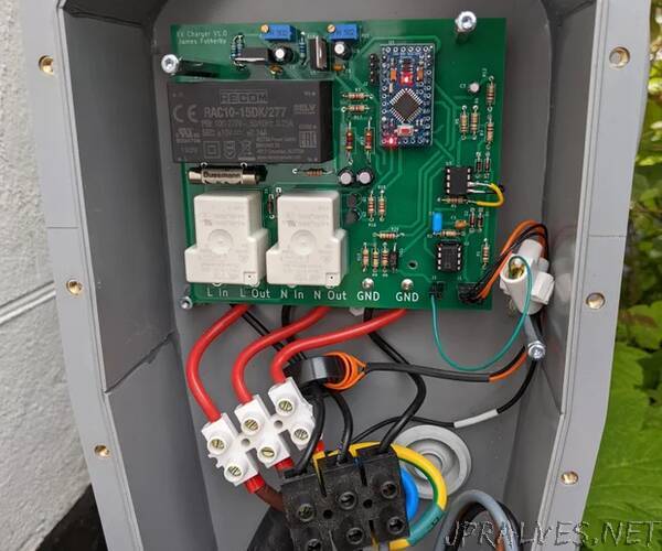
The SWA cable enters the Zappi enclosure through an outdoor water resistant gland. The live and neutral pass together through a current transformer before attaching to the PCB.
Ground Current Detection
One of the most important safety mechanisms to include is a ground current detection system. The chassis of the car is grounded via the earth wire through the charging plug. The earth supply comes from the consumer unit (we have TN-C-S supply).
There is quite a bit of theory behind grounding systems. John Ward has some instructional YouTube videos on the topic which I have watched. He discusses the problem of PEN faults etc. It’s worth spending the time educating yourself about earthing if you are doing any electrical work.
Although unlikely, it is possible for a fault to occur such that a live wire contacts the car chassis. Perhaps it’s pulled loose inside the car somewhere and is touching the chassis or perhaps a wet connector is bridging a path to the chassis.
Either way the live will source current into the chassis which will drain straight to ground (In a TN-C-S supply the ground and neutral conductors are bonded at the consumer unit). The amount of current will depend on the resistance of the faulty bridge. (water is unlikely to allow many amps to flow). Given the chassis is well earthed, it shouldn’t rise up in voltage enough to present a shock hazard to someone that touches it.
Nevertheless, this is a fault situation that should be detected and dealt with. If some water is bridging the live to the chassis perhaps a couple of amps will flow (not enough to trip the 50A MCB for the charger) but enough to cause localised heating and further damage.
So we need to measure current flowing to ground (should be zero in normal operation). If this is more than 20 mA we want to isolate the car by opening the relays. The reason RCDs typically trip at 5-30mA is because this amount of current for a couple hundred milliseconds doesn’t cause permanent injury to humans. I like the wikipedia article on electrical injury.”