
“I had a really difficult time understanding exactly what 555 timer circuits do and how they work. Most explanations online refer to their functionality when paired with RC series, but not exactly what logical interactions between the different input pins are.
To wrap my head around what was going on, I conducted some experiments much like those I did to understand how BJT transistors work. I used
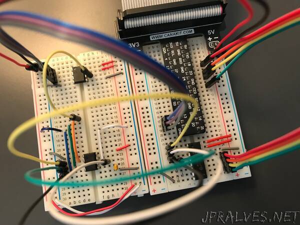
a Raspberry Pi to control the experiments and log the results
a TLC555 chip, which came as a part of my Adafruit Parts Pal
an MCP41010 digital potentiometer to vary the input voltages on different 555 pins
an MCP3008 analog-to-digital converter to read the 555’s output voltage pin
Given that the 555 timer has four input pins (TRIG, RESET, THRES, and CONT) and one relevant output pin (OUT), the idea is to hold three of the input pins fixed, then vary the fourth with the MCP41010 and measure the effect on the OUT pin with the MCP3008.”