

Microchip Technology is an American manufacturer of microcontroller, memory and analog semiconductors. Its products include microcontrollers (PICmicro, dsPIC / PIC24, PIC32, AVR, AVR32 and SAM), Serial EEPROM devices, Serial SRAM devices, KEELOQ devices, radio frequency (RF) devices, thermal, power and battery management analog devices, as well as linear, interface and mixed signal devices. Some of the interface devices include USB, ZigBee/MiWi, Controller Area Network, LoRa, SIGFOX and Ethernet.
24LC256 I/P - 256K I2C CMOS Serial EEPROM
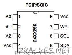
The Microchip Technology Inc. 24AA256/24LC256/24FC256 (24XX256*) is a 32K x 8 (256 Kbit) Serial Electrically Erasable PROM, capable of operation across a broad voltage range (1.7V to 5.5V). It has been developed for advanced, low-power applications such as personal communications or data acquisition. This device also has a page write capability of up to 64 bytes of data. This device is capable of both random and sequential reads up to the 256K boundary. Functional address lines allow up to eight devices on the same bus, for up to 2 Mbit address space. This device is available in the standard 8-pin plastic DIP, SOIC, TSSOP, MSOP and DFN packages.
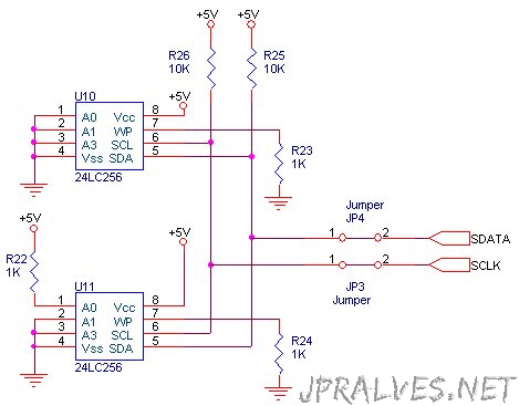
Circuit
PIC32MX220F032B-I/SP - 32-bit Microcontroller
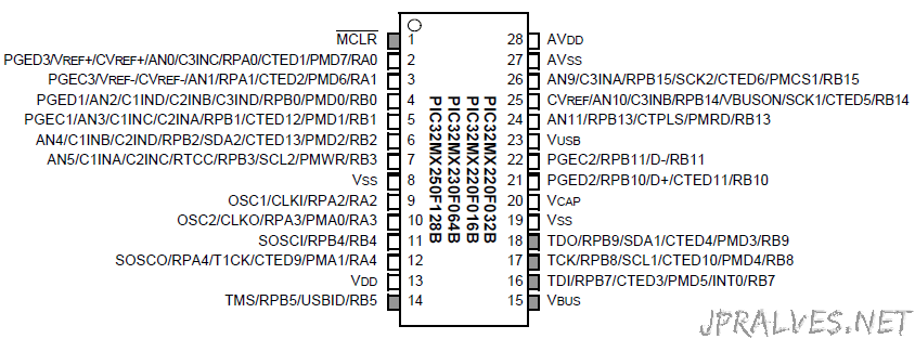
Microchip’s PIC32 “MX1” and “MX2” MCUs are the smallest and lowest-cost PIC32 microcontrollers, and are the first PIC32s to feature dedicated audio and capacitive-sensing peripherals. These MCUs include a host of additional useful features that make them suitable for applications in the consumer, industrial, medical and automotive markets.
Rated for operation up to 105°C, the PIC32 MX1 and MX2 MCUs include up to 128 KB of Flash, and 32 KB of SRAM; two I²S interfaces for audio processing; Microchip’s Charge Time Measurement Unit (CTMU) peripheral for adding mTouch™ capacitive touch buttons or advanced sensors; and an 8-bit Parallel Master Port (PMP) interface for graphics or external memory.
PIC24F32KA301 - 16-bit Microcontroller
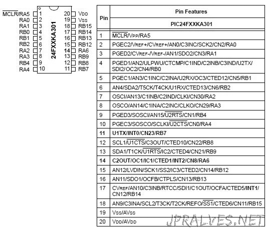
PIC24 16-bit Microcontroller featuring nanoWatt XLP for eXtreme Low Power consumption. Designed for power constrained and battery powered applications. Features unique peripherals like DSBOR, DSWDT and RTCC which run in Deep Sleep mode for industry leading low power performance.
MCP3008-I/P - 8-Channel 10-Bit A/D Converters
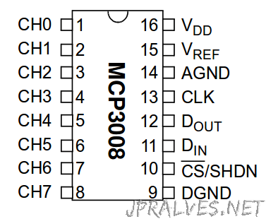
The MCP3008 10-bit Analog-to-Digital Converter (ADC) combines high performance and low power consumption in a small package, making it ideal for embedded control applications. The MCP3008 features a successive approximation register (SAR) architecture and an industry-standard SPI serial interface, allowing 10-bit ADC capability to be added to any PIC® microcontroller. The MCP3008 features 200k samples/second, 8 input channels, low power consumption (5nA typical standby, 425µA typical active), and is available in 16-pin PDIP and SOIC packages. Applications for the MCP3008 include data acquisition, instrumentation and measurement, multi-channel data loggers, industrial PCs, motor control, robotics, industrial automation, smart sensors, portable instrumentation and home medical appliances.
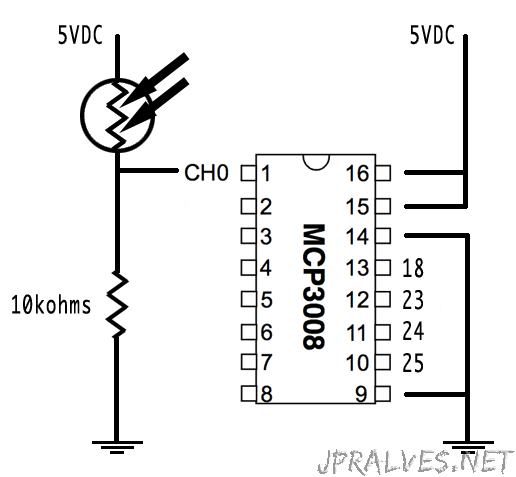
Circuit
MCP23017-E/SP - 16-Bit I/O Expander with Serial Interface
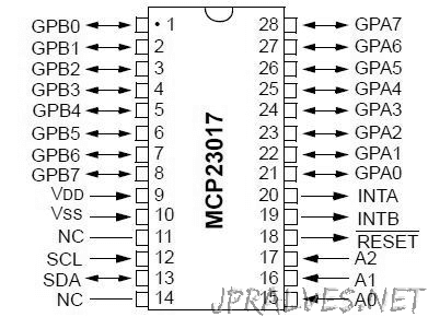
The MCP23017/MCP23S17 (MCP23X17) device family provides 16-bit, general purpose parallel I/O expansion for I2C bus or SPI applications. The two devices differ only in the serial interface.
- MCP23017 – I2C interface
- MCP23S17 – SPI interface
The MCP23X17 consists of multiple 8-bit configuration registers for input, output and polarity selection. The system master can enable the I/Os as either inputs or outputs by writing the I/O configuration bits (IODIRA/B). The data for each input or output is kept in the corresponding input or output register. The polarity of the Input Port register can be inverted with the Polarity
Inversion register. All registers can be read by the system master.
The 16-bit I/O port functionally consists of two 8-bit ports (PORTA and PORTB). The MCP23X17 can be configured to operate in the 8-bit or 16-bit modes via IOCON.BANK.
There are two interrupt pins, INTA and INTB, that can be associated with their respective ports, or can be logically OR’ed together so that both pins will activate if either port causes an interrupt.
The interrupt output can be configured to activate under two conditions (mutually exclusive):
1. When any input state differs from its corresponding Input Port register state. This is used to indicate to the system master that an input state has changed.
2. When an input state differs from a preconfigured register value (DEFVAL register). The Interrupt Capture register captures port values at the time of the interrupt, thereby saving the condition that caused the interrupt.
The Power-on Reset (POR) sets the registers to their default values and initializes the device state machine. The hardware address pins are used to determine the device address.
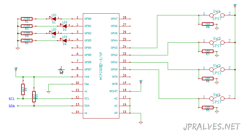
Circuit
PIC16F1705/9/IP - 8-bit PIC Microcontrollers
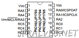
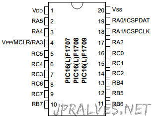
PIC16(L)F1705/9 microcontrollers combine Intelligent Analog integration with low cost and extreme low-power (XLP) to suit a variety of general purpose applications. These 14 and 20-pin devices deliver on-chip Op Amps, Core Independent Peripherals (CLC and COG), Peripheral Pin Select and Zero-Cross Detect, providing for increased design flexibility
Features
- 8 Kwords Flash Program Memory
- 1 Kbytes Data SRAM
- 18 I/O Pins
- Four 8-bit Timers / One 16-bit Timer
- 2 x High-Speed Comparators
- 2 x Op Amps
- 12ch x 10-bit ADC
- One 8-bit DAC
- Zero Cross Detect
- 2 x CCP / 2 x PWM
- 1 x COG
- 1 x EUSART
- 1 x I2C/SPI
- 3 x CLC
MCP602-I/P - Operational Amplifiers - Op Amps Dual 2.7V
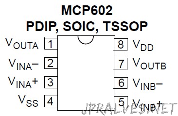
The MCP602 dual operational amplifier (op amp) has a gain bandwidth product of 2.8 MHz with low typical operating current of 230 uA and an offset voltage that is less than 2 mV. The MCP602 uses Microchip’s advanced CMOS technology, which provides low bias current, high-speed operation, high open-loop gain and rail-to-rail output swing. The MCP602 operates with a single supply voltage that can be as low as 2.7V, while drawing less than 325 of quiescent current per amplifier. The MCP602 is available in standard 8-lead PDIP, SOIC and TSSOP packages. This amplifier is ideal for industrial process control, low-power battery-operated devices, portable equipment, data acquisition equipment, test equipment and low-end audio applications.
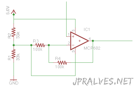
Circuit
MCP1700-5002E - Low Quiescent Current LDO
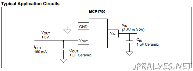
The MCP1700 is a CMOS low dropout positive voltage regulator which can source up to 250mA of current with an extremely low input-output voltage differential of 178mV at 250mA. The low dropout voltage combined with the low current consumption of only 1.6µA makes this part ideal for battery operation. The low voltage differential (dropout voltage) extends battery operating lifetime. The MCP1700 is stable with 1.0µF ceramic output capacitor. It also permits high currents in small packages when operated with minimum VIN – VOUT differentials. The circuit also incorporates short-circuit protection & over temperature protection to ensure maximum reliability.
Features
- Extremely Low Operating Current for Longer Battery Life (1.6 uA typical)
- Very Low Dropout Voltage (178 mV at full load)
- Rated 250mA Output Current
- High Output Voltage Accuracy (±0.4% typical)
- Over-Current and Over-Temperature Protection
- Pin Compatible Upgrade for Bipolar Regulators & TC55 with Vin Max <6V
- Requires only 1 µF Ceramic Output Capacitance
MCP1700-3302 - Low Quiescent Current LDO
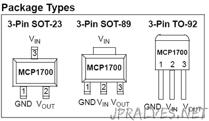
The MCP1700 is a family of CMOS low dropout (LDO) voltage regulators that can deliver up to 250 mA of current while consuming only 1.6 µA of quiescent current (typical). The input operating range is specified from 2.3V to 6.0V, making it an ideal choice for two and three primary cell battery-powered applications, as well as single cell Li-Ion-powered applications. The MCP1700 is capable of delivering 250 mA with only 178 mV of input to output voltage differential (VOUT = 2.8V). The output voltage tolerance of the MCP1700 is typically ±0.4% at +25°C and ±3% maximum over the operating junction temperature range of -40°C to +125°C. Output voltages available for the MCP1700 range from 1.2V to 5.0V. The LDO output is stable when using only 1 µF output capacitance. Ceramic, tantalum or aluminum electrolytic capacitors can all be used for input and output. Overcurrent limit and overtemperature shutdown provide a robust solution for any application. Package options include SOT-23, SOT-89, TO-92 and 2x2 DFN-6.
Features
- Extremely Low Operating Current for Longer Battery Life (1.6 uA typical)
- Very Low Dropout Voltage (178 mV at full load)
- Rated 250mA Output Current
- High Output Voltage Accuracy (±0.4% typical)
- Over-Current and Over-Temperature Protection
- Pin Compatible Upgrade for Bipolar Regulators & TC55 with Vin Max <6V
- Requires only 1 µF Ceramic Output Capacitance
Circuit
PIC16LF1554 - 20-Pin Flash, 8-Bit Microcontrollers with XLP Technology
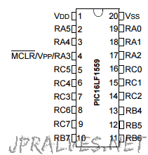
The PIC16LF1554/1559 microcontrollers with Microchip enhanced mid-range core deliver unique on-chip features for
the design of mTouch ® solutions and general purpose applications in 14/20-pin count packages. Two 10-bit high-speed ADCs with automated hardware CVD modules connect to up to 17 analog channels to achieve a total sampling rate of 600k samples per second. Combined with two PWMs and multiple communication peripherals, this microcontroller family is an excellent solution to implement low-power and noise-robust capacitive sensing and other front-end sampling applications with minimal software overhead.
Features
- Dual Analog to 10-bit Digital Converter (ADC)
- 12 Channel 10-bit ADC
- Advanced Controls for mTouch CVD (Capacitive Voltage Divider)
- Voltage Reference
- MI2C, SPI, UART
- 2 PWMs
- 25mA Source/Sink current I/O
- 32 MHz internal oscillator
- Low Power Brown Out Reset (LPBOR)
- Extended Watchdog Timer (WDT)
- In-Circuit Debug
- Operating Voltage : 1.8V – 3.6V
High-Performance RISC CPU
- Only 49 Instructions to Learn
- Operating Speed:
- DC – 32 MHz clock input
- DC – 125 ns instruction cycle
- Interrupt Capability with Automatic Context Saving
- 16-Level Deep Hardware Stack with Optional Overflow/Underflow Reset
- Direct, Indirect and Relative Addressing modes:
- Two full 16-bit File Select Registers (FSRs)
- FSRs can read program and data memory
MCP41010 - Mixel Signal - Digital potentiometers
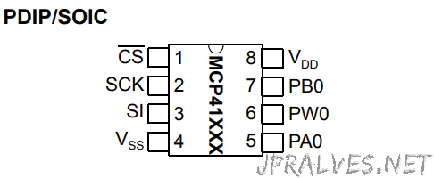
The MCP41XXX and MCP42XXX devices are 256-position, digital potentiometers available in 10 kΩ, 50 kΩ and 100 kΩ resistance versions. The MCP41XXX is a single-channel device and is offered in an 8-pin PDIP or SOIC package. The MCP42XXX contains two independent channels in a 14-pin PDIP, SOIC or TSSOP package. The wiper position of the MCP41XXX/42XXX varies linearly and is controlled via an industry-standard SPI interface. The devices consume <1 µA during static operation. A software shutdown feature is provided that disconnects the “A” terminal from the resistor stack and simultaneously connects the wiper to the “B” terminal. In addition, the dual MCP42XXX has a SHDN pin that performs the same function in hardware. During shutdown mode, the contents of the wiper register can be changed and the potentiometer returns from shutdown to the new value. The wiper is reset to the mid-scale position (80h) upon power-up. The RS (reset) pin implements a hardware reset and also returns the wiper to mid-scale. The MCP42XXX SPI interface includes both the SI and SO pins, allowing daisy-chaining of multiple devices. Channel-to-channel resistance matching on the MCP42XXX varies by less than 1%. These devices operate from a single 2.7 - 5.5V supply and are specified over the extended and industrial temperature ranges.
The MCP41010 is a single-channel, 8-bit digital potentiometer features 10kΩ end-to-end resistance value with an SPI serial interface. The wiper position varies linearly and is controlled via the SPI interface. The MCP41010 has outstanding AC and DC characteristics, and consumes <1 µA during static operation. Applications for the MCP41010 digital potentiometer include audio equipment (volume and tone controls), servo-motor control, battery charging and control, communications (line impedance matching), power supplies, instrumentation (gain, offset adjust), LCD contrast control and programmable filters. The MCP41010 is available in 8-pin PDIP and SOIC packages.
Additional Features
- Single Resistor Network
- Potentiometer or Rheostat configuration options
- Resistor Network Resolution
- 8-bit: 255 Resistors (256 Steps)
- RAB Resistances options of:
- 10kΩ
- Zero-Scale to Full-Scale Wiper operation
- INL: 1LSB (max)
- DNL: 1LSB (max)
- SPI Compatible Serial interface
- Standby current: 1uA (max)
- Wide Operating Voltage: 2.7V to 5.5V
- Wide Bandwidth (-3dB) Operation: 1 MHz (typ.)
- Extended temperature range: -40°C to +125°C
| Name | Value |
|---|---|
| Temp. Range (°C) | -40 to +125 |
| Volatile / Non Volatile | Volatile |
| Number of Taps | 256 |
| Resistance (ohms) K | 10 |
| # per Package | 1 |
| INL (Max) | 1 |
| DNL (Max) | 1 |
| Interface | SPI |
Circuit
MCP41010 & Arduino Test
As you may have noticed, a digital potentiometer behaves the same as a mechanical potentiometer, except that instead of having a round handle that you can turn, it’s controlled by a digital interface. As a basic test, you can drive MCP41010 with the help of an Arduino UNO and its Serial Peripheral Interface (SPI) port. Note that SPI is a “synchronous” serial data bus — data can travel in both directions at the same time. On Arduino Uno (and compatible) boards, the SPI pins used are:
SS – D10 (you can use other digital pins, but D10 is the default)
MOSI – D11
MISO – D12
SCK – D13
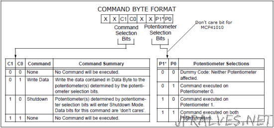
Just refer to the datasheet and note that to program the digital pot, you have to first send a “command byte” (to tell the chip what to do) and a “data byte” (to tell the chip which value of resistance to set, from 0 to 255). As found in the datasheet, “executing any command is accomplished by setting CS low and then clocking in a command byte followed by a data byte into the 16-bit shift register. The command is executed when CS is raised.” Now prepare your hardware setup as follows!
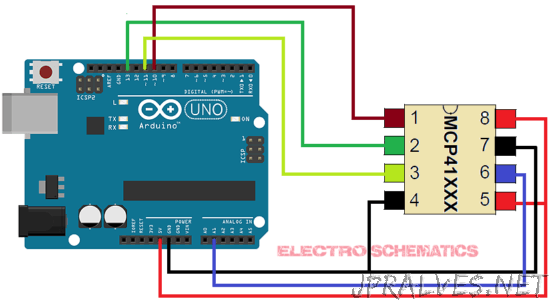
In the hardware setup, MCP41010 is connected to the Arduino via the Arduino’s SPI Interface. Potentiometer terminals A (pin 5) and B (pin 7) are connected to the Arduino 5-volt supply (5 V) and Ground (Gnd). The wiper terminal W (pin 6) is connected to the Analog Pin 1 (A1) of the Arduino. The pretty simple sketch (shown below) loaded into the Arduino selects the MCP41010 and cycles through all 256 wiper positions (about 39 Ω per step). The voltage at the analog pin is then read and displayed on the serial monitor.
#include <SPI.h>

const int CS = 10;
int PotWiperVoltage = 1;
int RawVoltage = 0;
float Voltage = 0;
void setup() {
   pinMode (CS, OUTPUT);
   Serial.begin(9600);
   SPI.begin(); // initialize SPI
}
void loop() {
   // move the wiper in one direction
   for (int level = 0; level < 255; level++)
   {
      MCP41010Write(level);
      delay(100);
      RawVoltage = analogRead(PotWiperVoltage);
      Voltage = (RawVoltage * 5.0 )/ 1024.0;
      Serial.print("Level = " );
      Serial.print(level);
      Serial.print("\t Voltage = ");
      Serial.println(Voltage,3);
   }
   delay(2000); // wait time
   // move the wiper in other direction
   for (int level = 255; level > 0; level--)
   {
      MCP41010Write(level);
      delay(100);
      RawVoltage = analogRead(PotWiperVoltage);
      Voltage = (RawVoltage * 5.0 )/ 1024.0;
      Serial.print("Level = " );
      Serial.print(level);
      Serial.print("\t Voltage = ");
      Serial.println(Voltage,3);
   }
   delay(2000);
}
void MCP41010Write(byte value)
{
   digitalWrite(CS,LOW); // select the chip
   SPI.transfer(B00010001); // command byte
   SPI.transfer(value); // data byte
   digitalWrite(CS,HIGH); // de-select the chip
}
Circuit from: Link