

Maxim Integrated is an American, publicly traded company that designs, manufactures, and sells analog and mixed-signal integrated circuits.
Maxim Integrated develops integrated circuits (ICs) for the automotive, industrial, communications, consumer, and computing markets.
DS1302 - Trickle-Charge Timekeeping Chip
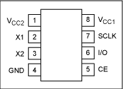
The DS1302 trickle-charge timekeeping chip contains a real-time clock/calendar and 31 bytes of static RAM. It communicates with a microprocessor via a simple serial interface. The real-time clock/calendar provides seconds, minutes, hours, day, date, month, and year information. The end of the month date is automatically adjusted for months with fewer than 31 days, including corrections for leap year. The clock operates in either the 24-hour or 12-hour format with an AM/PM indicator.
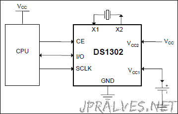
Interfacing the DS1302 with a microprocessor is simplified by using synchronous serial communication. Only three wires are required to communicate with the clock/RAM: CE, I/O (data line), and SCLK (serial clock). Data can be transferred to and from the clock/RAM 1 byte at a time or in a burst of up to 31 bytes. The DS1302 is designed to operate on very low power and retain data and clock information on less than 1µW.
The DS1302 is the successor to the DS1202. In addition to the basic timekeeping functions of the DS1202, the DS1302 has the additional features of dual power pins for primary and backup power supplies, programmable trickle charger for VCC1, and seven additional bytes of scratchpad memory.
Circuit
DS1307 - 64 x 8, Serial, I2C Real-Time Clock
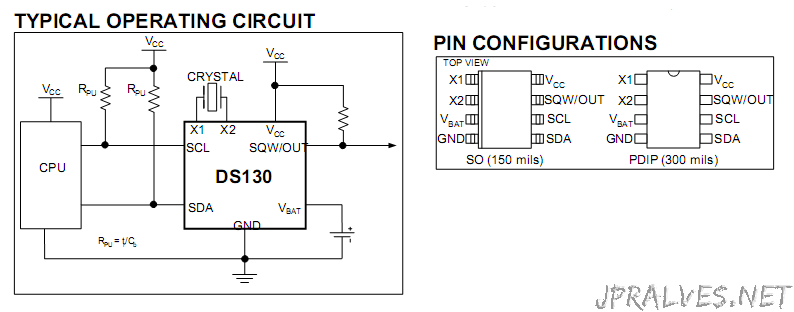
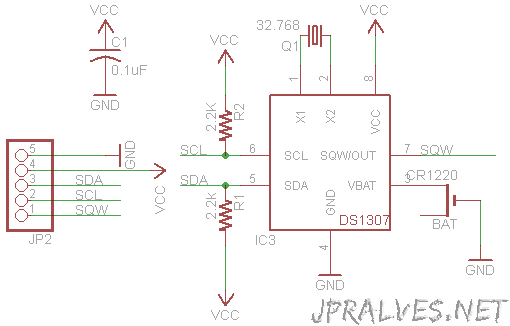
The DS1307 serial real-time clock (RTC) is a low-power, full binary-coded decimal (BCD) clock/calendar plus 56 bytes of NV SRAM. Address and data are transferred serially through an I²C, bidirectional bus. The clock/calendar provides seconds, minutes, hours, day, date, month, and year information. The end of the month date is automatically adjusted for months with fewer than 31 days, including corrections for leap year. The clock operates in either the 24-hour or 12-hour format with AM/PM indicator. The DS1307 has a built-in power-sense circuit that detects power failures and automatically switches to the backup supply. Timekeeping operation continues while the part operates from the backup supply.
Circuit
ICL7662 - CMOS Voltage Converter
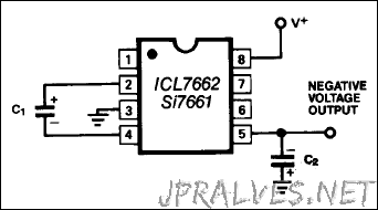
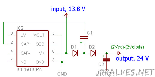
The ICL7662 is a monolithic high-voltage CMOS power supply circuit which offers unique performance advantages over previously available devices. The ICL7662 performs supply voltage conversion from positive to negative for an input range of +4.5V to +20.0V, resulting in complementary output voltages of -4.5V to -20V. Only 2 noncritical external capacitors are needed for the charge pump and charge reservoir functions. The ICL7662 can also function as a voltage doubler, and will generate output voltages up to +38.6V with a +20V input.
Circuit
MAX31855 - Cold-Junction Compensated Thermocouple-to-Digital Converter
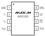
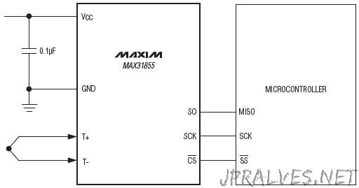
Maxim Integrated MAX31855 Cold-Junction Compensated Thermocouple-to-Digital Converters perform cold-junction compensation and digitize the signal from a K-, J-, N-, T-, S-, R-, or E-type thermocouple. The data is output in a signed 14-bit, SPI™-compatible, read-only format. Maxim Integrated MAX31855 converters resolve temperatures to 0.25°C, allow readings as high as +1800°C and as low as -270°C, and exhibit thermocouple accuracy of ±2°C for temperatures ranging from -200°C to +700°C for K-type thermocouples. Maxim Integrated MAX31855 Thermocouple-to-Digital Converters are ideal for use in a variety of applications, including automotive, HVAC, and industrial.
Circuit
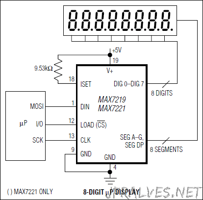
MAX7219CNG - Serially Interfaced, 8-Digit, LED Display Drivers
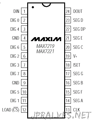
The MAX7219CNG is a compact, serial input/output common-cathode display driver that can interface microprocessors to 7-segment numeric LED displays of up to 8 digits, bar-graph displays, or 64 individual LEDs. Included on-chip are a BCD code-B decoder, multiplex scan circuitry, segment and digit drivers, and an 8x8 static RAM that stores each digit.
Communication with the MAX7219 is achieved through a convenient 4-wire serial interface (supports SPI). Individual digits may be addressed and updated without rewriting the entire display. Only one external resistor is required to set the segment current for all LEDs.
The IC also includes a 150μA low-power shutdown mode, analog and digital brightness control, a scanlimit register that allows the user to display from 1 to 8 digits, and a test mode that forces all LEDs on.
This device comes in a 24-pin DIP package.
Features
- 10MHz Serial Interface
- Individual LED Segment Control
- Decode/No-Decode Digit Selection
- 150μA Low-Power Shutdown (Data Retained)
- Digital and Analog Brightness Control
- Display Blanked on Power-Up
- Drive Common-Cathode LED Display
- Slew-Rate Limited Segment Drivers for Lower EMI (MAX7221)
- SPI, QSPI, MICROWIRE Serial Interface (MAX7221)
- 24-Pin DIP package
Circuit
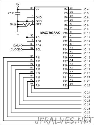
MAX7300ANI - 2-Wire-Interfaced, 2.5V to 5.5V, 20-Port or 28-Port I/O Expander
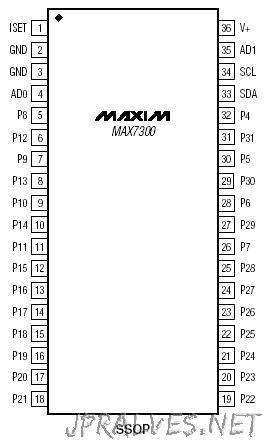
The MAX7300 compact, serial-interfaced, I/O expansion peripheral provides microprocessors with up to 28 ports. Each port is individually user configurable to either a logic input or logic output. Each port can be configured as either a push-pull logic output capable of sinking 10mA and sourcing 4.5mA, or a Schmitt logic input with optional internal pullup. Seven ports feature configurable transition detection logic, which generates an interrupt upon change of port logic level. The MAX7300 is controlled through an I2
C-compatible 2-wire serial interface, and uses four-level logic to allow 16 I2C addresses from only two select pins.
The MAX7300AAX and MAX7300ATL have 28 ports and are available in 36-pin SSOP and 40-pin TQFN packages, respectively. The MAX7300AAI and MAX7300ATI have 20 ports and are available in 28-pin SSOP and TQFN packages. For an SPI-interfaced version, refer to the MAX7301 data sheet. For a pin-compatible port expander with additional 24mA constant-current LED drive capability, refer to the MAX6956 data sheet.
Circuit
MAX6954APL - 4-Wire Interfaced, 2.7V to 5.5V LED Display Driver with I/O Expander and Key Scan
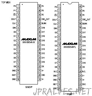
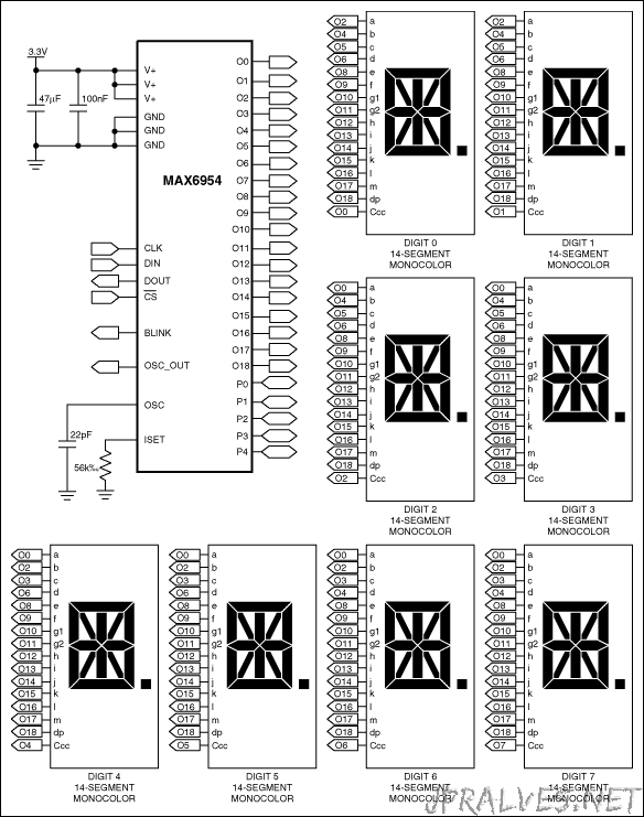
The MAX6954 is a compact display driver that interfaces microprocessors to a mix of 7-segment, 14-segment, and 16-segment LED displays through an SPI-/ QSPI™-compatible 4-wire serial interface. The serial interface may be cascaded through multiple devices. The MAX6954 drives up to 16 digits 7-segment, 8 digits 14-segment, 8 digits 16-segment, or 128 discrete LEDs, while functioning from a supply voltage as low as 2.7V. The driver includes five I/O expander (or GPIO) lines, some or all of which may be configured as a key-switch reader, which automatically scans and debounces a matrix of up to 32 switches. Included on chip are full 14- and 16-segment ASCII 104-character fonts, a hexadecimal font for 7-segment displays, multiplex scan circuitry, anode and cathode drivers, and static RAM that stores each digit. The maximum segment current for the display digits is set using a single external resistor. Digit intensity can be independently adjusted using the 16-step internal digital brightness control. The MAX6954 includes a low-power shutdown mode, a scan-limit register that allows the user to display from 1 to 16 digits, segment blinking (synchronized across multiple drivers, if desired), and a test mode, which forces all LEDs on. The LED drivers are slew-rate limited to reduce EMI.
Schematic
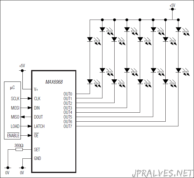
MAX6968APL - 8-Port, 5.5V Constant-Current LED Driver
The MAX6968 serial-interfaced LED driver provides eight open-drain, constant-current sinking LED driver outputs rated at 5.5V. The MAX6968 operates from a 3V to 5.5V supply. The MAX6968 supply and the LEDs’ supply or supplies may power up in any order. The constant-current outputs are programmed together to up to 55mA using a single external resistor. The MAX6968 operates with a 25Mb, industry-standard, 4- wire serial interface. The MAX6968 uses the industry-standard shift-registerplus-latch-type serial interface. The driver accepts data shifted into an 8-bit shift register using data input DIN and clock input CLK. Input data appears at the output DOUT eight clock cycles later to allow cascading of multiple MAX6968s. The latch-enable input LE loads the 8 bits of shift register data into an 8-bit output latch to set which LEDs are on and which are off. The outputenable input OE gates all eight outputs on and off, and is fast enough to be used as a PWM input for LED intensity control. For applications requiring LED fault detection, refer to the MAX6977 data sheet that automatically detects open-circuit LEDs. For safety-related applications requiring a watchdog timer, refer to the MAX6978 data sheet that includes a fail-safe feature that blanks the display if the serial interface becomes inactive for more than 1s. The MAX6968 is one of a family of 12 shift-register-pluslatch-type LED drivers. The family includes 8-port and 16-port types, with 5.5V- or 36V-rated LED outputs, with and without open-circuit LED detection and watchdog. All versions operate from a 3V to 5.5V supply, and are specified over the -40°C to +125°C temperature range
DS18B20 - Programmable Resolution 1-Wire Digital Thermometer
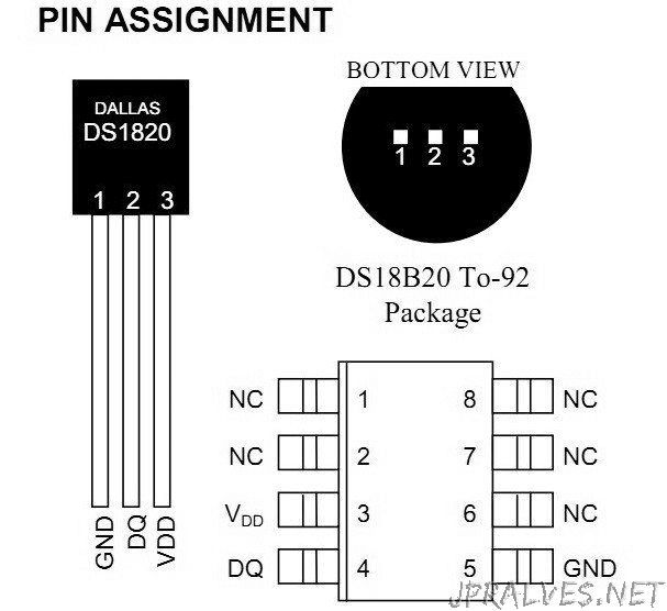
The DS18B20 digital thermometer provides 9-bit to 12-bit Celsius temperature measurements and has an alarm function with nonvolatile user-programmable upper and lower trigger points. The DS18B20 communicates over a 1-Wire® bus that by definition requires only one data line (and ground) for communication with a central microprocessor. It has an operating temperature range of -55°C to +125°C and is accurate to ±0.5°C over the range of -10°C to +85°C. In addition, the DS18B20 can derive power directly from the data line (“parasite power”), eliminating the need for an external power supply.
Each DS18B20 has a unique 64-bit serial code, which allows multiple DS18B20s to function on the same 1-Wire bus. Thus, it is simple to use one microprocessor to control many DS18B20s distributed over a large area. Applications that can benefit from this feature include HVAC environmental controls, temperature monitoring systems inside buildings, equipment, or machinery, and process monitoring and control systems.
Key Features
- Unique 1-Wire® Interface Requires Only One Port Pin for Communication
- Reduce Component Count with Integrated Temperature Sensor and EEPROM
- Measures Temperatures from -55°C to +125°C (-67°F to +257°F)
- ±0.5°C Accuracy from -10°C to +85°C
- Programmable Resolution from 9 Bits to 12 Bits
- No External Components Required
- Parasitic Power Mode Requires Only 2 Pins for Operation (DQ and GND)
- Simplifies Distributed Temperature-Sensing Applications with Multidrop Capability
- Each Device Has a Unique 64-Bit Serial Code Stored in On-Board ROM
- Flexible User-Definable Nonvolatile (NV) Alarm Settings with Alarm Search Command Identifies Devices with Temperatures Outside Programmed Limits
- Available in 8-Pin SO (150 mils), 8-Pin µSOP, and 3-Pin TO-92 Packages
Applications/Uses
- Agricultural Equipment
- Audio Equipment
- Climate Control
- GPS Devices
- Hard Disk Drive
- Medical Equipment
- Set-Top Boxes
- Telecommunications
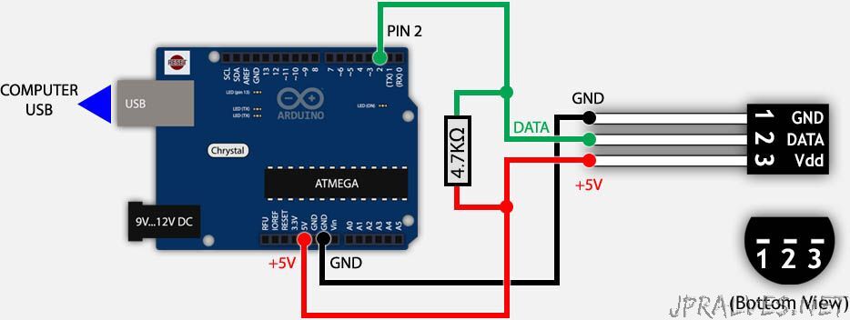
Circuit: How to measure temperature with your Arduino and a DS18B20
(Link)
#include <OneWire.h>

// OneWire DS18S20, DS18B20, DS1822 Temperature Example
//
// http://www.pjrc.com/teensy/td_libs_OneWire.html
//
// The DallasTemperature library can do all this work for you!
// http://milesburton.com/Dallas_Temperature_Control_Library

OneWire  ds(2);  // on pin 10 (a 4.7K resistor is necessary)

void setup(void) {
  Serial.begin(9600);
}

void loop(void) {
  byte i;
  byte present = 0;
  byte type_s;
  byte data[12];
  byte addr[8];
  float celsius, fahrenheit;

  if ( !ds.search(addr)) {
    Serial.println("No more addresses.");
    Serial.println();
    ds.reset_search();
    delay(250);
    return;
  }

  Serial.print("ROM =");
  for( i = 0; i < 8; i++) {
    Serial.write(' ');
    Serial.print(addr[i], HEX);
  }

  if (OneWire::crc8(addr, 7) != addr[7]) {
      Serial.println("CRC is not valid!");
      return;
  }
  Serial.println();

  // the first ROM byte indicates which chip
  switch (addr[0]) {
    case 0x10:
      Serial.println("  Chip = DS18S20");  // or old DS1820
      type_s = 1;
      break;
    case 0x28:
      Serial.println("  Chip = DS18B20");
      type_s = 0;
      break;
    case 0x22:
      Serial.println("  Chip = DS1822");
      type_s = 0;
      break;
    default:
      Serial.println("Device is not a DS18x20 family device.");
      return;
  }

  ds.reset();
  ds.select(addr);
  ds.write(0x44);        // start conversion, use ds.write(0x44,1) with parasite power on at the end

  delay(1000);     // maybe 750ms is enough, maybe not
  // we might do a ds.depower() here, but the reset will take care of it.

  present = ds.reset();
  ds.select(addr);
  ds.write(0xBE);         // Read Scratchpad

  Serial.print("  Data = ");
  Serial.print(present, HEX);
  Serial.print(" ");
  for ( i = 0; i < 9; i++) {           // we need 9 bytes
    data[i] = ds.read();
    Serial.print(data[i], HEX);
    Serial.print(" ");
  }
  Serial.print(" CRC=");
  Serial.print(OneWire::crc8(data, 8), HEX);
  Serial.println();

  // Convert the data to actual temperature
  // because the result is a 16 bit signed integer, it should
  // be stored to an "int16_t" type, which is always 16 bits
  // even when compiled on a 32 bit processor.
  int16_t raw = (data[1] << 8) | data[0];
  if (type_s) {
    raw = raw << 3; // 9 bit resolution default
    if (data[7] == 0x10) {
      // "count remain" gives full 12 bit resolution
      raw = (raw & 0xFFF0) + 12 - data[6];
    }
  } else {
    byte cfg = (data[4] & 0x60);
    // at lower res, the low bits are undefined, so let's zero them
    if (cfg == 0x00) raw = raw & ~7;  // 9 bit resolution, 93.75 ms
    else if (cfg == 0x20) raw = raw & ~3; // 10 bit res, 187.5 ms
    else if (cfg == 0x40) raw = raw & ~1; // 11 bit res, 375 ms
    //// default is 12 bit resolution, 750 ms conversion time
  }
  celsius = (float)raw / 16.0;
  fahrenheit = celsius * 1.8 + 32.0;
  Serial.print("  Temperature = ");
  Serial.print(celsius);
  Serial.print(" Celsius, ");
  Serial.print(fahrenheit);
  Serial.println(" Fahrenheit");
}
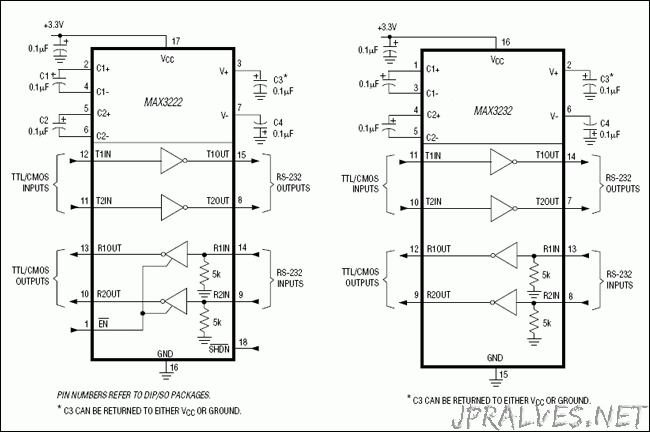
MAX3232 - 3.0V to 5.5V, Low-Power, up to 1Mbps, True RS-232 Transceivers Using Four 0.1µF External Capacitors
The MAX3222/MAX3232/MAX3237/MAX3241 transceivers have a proprietary low-dropout transmitter output stage enabling true RS-232 performance from a 3.0V to 5.5V supply with a dual charge pump. The devices require only four small 0.1µF external charge-pump capacitors. The MAX3222, MAX3232, and MAX3241 are guaranteed to run at data rates of 120kbps while maintaining RS-232 output levels. The MAX3237 is guaranteed to run at data rates of 250kbps in the normal operating mode and 1Mbps in the MegaBaud™ operating mode, while maintaining RS-232 output levels.
The MAX3222/MAX3232 have 2 receivers and 2 drivers. The MAX3222 features a 1µA shutdown mode that reduces power consumption and extends battery life in portable systems. Its receivers remain active in shutdown mode, allowing external devices such as modems to be monitored using only 1µA supply current. The MAX3222 and MAX3232 are pin, package, and functionally compatible with the industry-standard MAX242 and MAX232, respectively.
The MAX3241 is a complete serial port (3 drivers/5 receivers) designed for notebook and subnotebook computers. The MAX3237 (5 drivers/3 receivers) is ideal for fast modem applications. Both these devices feature a shutdown mode in which all receivers can remain active while using only 1µA supply current. Receivers R1 (MAX3237/MAX3241) and R2 (MAX3241) have extra outputs in addition to their standard outputs. These extra outputs are always active, allowing external devices such as a modem to be monitored without forward biasing the protection diodes in circuitry that may have VCC completely removed.
The MAX3222, MAX3237, and MAX3241 are available in space-saving TSSOP and SSOP packages.
Key Features
- For Smaller Packaging:
- MAX3228E/MAX3229E: +2.5V to +5.5V RS-232 Transceivers in UCSP™
- For Integrated ESD Protection:
- MAX3222E/MAX3232E/MAX3237E/MAX3241E/MAX3246E: ±15kV ESD-Protected, Down to 10nA, 3.0V to 5.5V, Up to 1Mbps, True RS-232 Transceivers
- For Low-Voltage or Data Cable Applications:
- MAX3380E/MAX3381E: +2.35V to +5.5V, 1µA, 2Tx/2Rx RS-232 Transceivers with ±15kV ESD-Protected I/O and Logic Pins
Applications/Uses
- Battery-Powered Equipment
- Handheld Equipment
- High-Speed Modems
- Notebook, Subnotebook, and Palmtop Computers
- Peripherals
- Printers
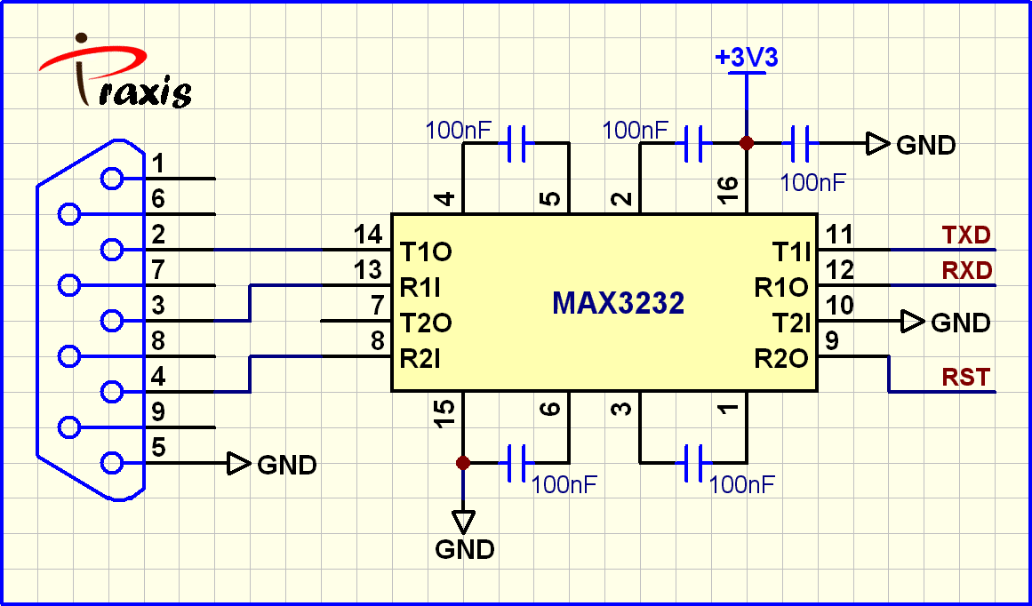
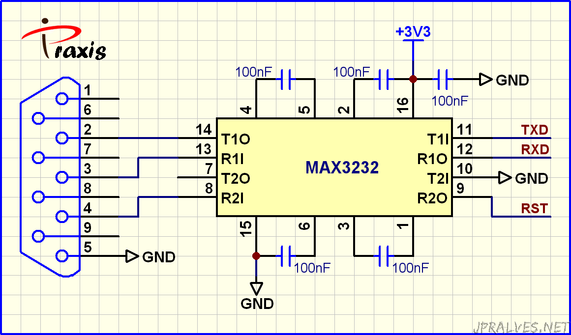
Circuit: Max3232 protoboard interface
(Link)
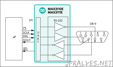
MAX3110 - SPI/MICROWIRE-Compatible UART and ±15kV ESD-Protected RS-232 Transceivers with Internal Capacitors
The MAX3110E/MAX3111E combine a full-featured universal asynchronous receiver/transmitter (UART) with ±15kV ESD-protected RS-232 transceivers and integrated charge-pump capacitors into a single 28-pin package for use in space-, cost-, and power-constrained applications. The MAX3110E/MAX3111E also feature an SPI™/QSPI™/MICROWIRE™-compatible serial interface to save additional board space and microcontroller (µC) I/O pins.
A proprietary low-dropout output stage enables the 2-driver/2-receiver interface to deliver true RS-232 performance down to VCC = +3V (+4.5V for MAX3110E) while consuming only 600µA. The receivers remain active in a hardware/software-invoked shutdown, allowing external devices to be monitored while consuming only 10µA. Each device is guaranteed to operate at up to 230kbps while maintaining true EIA/TIA-232 output voltage levels.
The MAX3110E/MAX3111E’s UART includes a crystal oscillator and baud-rate generator with software-programmable divider ratios for all common baud rates from 300baud to 230kbaud. The UART features an 8-word-deep receive FIFO that minimizes processor overhead and provides a flexible interrupt with four maskable sources. Two control lines (one input and one output) are included for hardware handshaking.
The UART and RS-232 functions can be used together or independently since the two functions share only supply and ground connections (the MAX3110E/MAX3111E are hardware- and software-compatible with the MAX3100 and MAX3222E).
Key Features
- Integration Reduces Cost and Board Space
- Integrated RS-232 Transceiver and UART in a Single 28–Pin Package
- Guaranteed 230kbps Data Rate
- SPI/QSPI/MICROWIRE-Compatible µC Interface
- Internal Charge-Pump Capacitors—No External Components Required
- Low-Power Operation Reduces Thermal Dissipation
- True RS-232 Operation Down to VCC = +3V (MAX3111E)
- Single-Supply Operation
- +5V (MAX3110E)
- +3.3V (MAX3111E)
- 600µA Supply Current
- 10µA Shutdown Supply Current with Receiver Interrupt Active
- Hardware/Software-Compatible with MAX3100 and MAX3222E
Applications/Uses
- Handheld/Battery-Powered Equipment
- Handy Terminals
- Industrial Front-Panel Interfaces
- Point-of-Sale (POS) Devices
- Telecom/Networking Diagnostic Ports
MAX6920 - 12-Output, 76V, Serial-Interfaced VFD Tube Driver
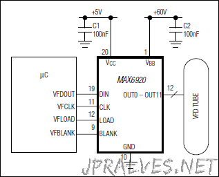
The MAX6920 is a 12-output, 76V, vacuum fluorescent display (VFD) tube driver that interfaces a multiplexed VFD tube to a VFD controller such as the MAX6850-MAX6853 or to a microcontroller. The MAX6920 is also ideal for driving either static VFD tubes or telecom relays. Data is inputted using an industry-standard 4-wire serial interface (CLOCK, DATA, LOAD, BLANK) for compatibility with both industry-standard drivers and Maxim’s VFD controllers.For easy display control, the active-high BLANK input forces all driver outputs low, turning the display off, and automatically puts the MAX6920 into shutdown mode. Display intensity may also be controlled by pulse-width modulating the BLANK input.The MAX6920 has a serial interface data output pin, DOUT, allowing any number of devices to be cascaded on the same serial interface.The MAX6920 is available in a 20-pin SO package. Maxim also offers VFD drivers with either 20 (MAX6921/MAX6931) or 32 outputs (MAX6922 and MAX6932).
Key Features
- 5MHz Industry-Standard 4-Wire Serial Interface
- 3V to 5.5V Logic Supply Range
- 8V to 76V Grid/Anode Supply Range
- Push-Pull CMOS High-Voltage Outputs
- Outputs can Source 40mA, Sink 4mA Continuously
- Outputs can Source 75mA Repetitive Pulses
- Outputs can be Paralleled for Higher Current Drive
- Any Output can be Used as a Grid or an Anode Driver
- Blank Input Simplifies PWM Intensity Control
- Small 20-Pin SO Package
- -40°C to +125°C Temperature Range