
“This guide will walk you through creating a USB microphone on the Raspberry Pi Pico using the RP2040’s PIO, DMA, and USB capabilities.
Introduction
This guide will walk through how to create your own USB microphone device using a Raspberry Pi Pico board and an external digital microphone. This project will leverage the Programming I/O (PIO), Direct Memory Access (DMA), and Universal Serial Bus (USB) capabilities of the boards RP2040 microcontroller (MCU).
USB
USB is an extremely popular standard, released in 1996, for wired computer peripherals, such as keyboards, mice, printers, scanners, and microphones.
The Raspberry Pi Pico board’s RP2040 MCU has a “USB 1.1 Host/Device” feature, which allows you to either connect to an existing USB peripheral device (host mode) or create your own USB peripheral (device mode). The Raspberry Pi Pico SDK uses the TinyUSB library as its USB software stack.
The Tiny USB library is “An open source cross-platform USB stack for embedded system” that supports several types of MCU’s including the Raspberry Pi RP2040. and has support for both device and host mode. We can use it’s built in USB Audio Class support to transform our Pico into a USB microphone device.
Selecting a microphone
The RP2040 MCU has a built-in 4 channel Analog-to-digital converter (ADC) feature with 12-bit precision, this could be used to collect audio from an external analog microphone, however we found the audio quality from the analog microphone to contain a lot of noise, so will be using a digital microphone instead.
There are two common interfaces for digital microphones:
Pulse Density Modulation (PDM)
Inter-IC Sound (I2S)
While the RP2040 does not have built-in support for both of these interface types, the super flexible Programmable I/O (PIO) feature can be used to create our own PDM or I2S peripheral interface in software. I will generate an output clock signal to the microphone on one pin and use another pin to receive data from the microphone. For this guide we’ll be using the Adafruit PDM MEMS Microphone Breakout board.
How does PDM work?
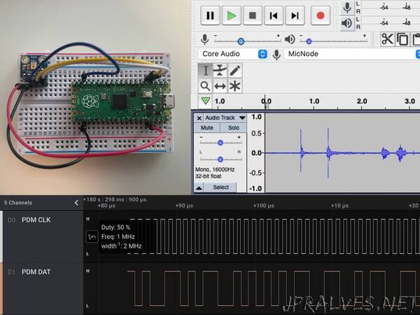
When the PDM microphone receives the clock signal, it outputs a 0 or 1 signal based on the analog audio value it captures from the microphone. To capture audio at 16, 000 samples per second (16 kHz), the PDM microphone’s clock input must be driven at 1.024 MHz = 64 x 16kHz and then the PDM’s microphone data single can be filtered and downsampled. For each sample, the 0 or 1 output for 64 values are averaged to create a single 16-bit value between -32678 and 32767 for the sample.”